Supercharge Your Innovation With Domain-Expert AI Agents!

Lens Meter

a technology of lens meter and near vision portion, which is applied in the field of lens meter, can solve the problems of inability to accurately measure the near vision portion, lack of near vision portion parts, and inability to make accurate measurements of the near vision portion of conventional lens meter, etc., and achieve the effect of accurate and easy measurement of the near vision portion

Active Publication Date: 2009-01-22
NIDEK CO LTD
View PDF10 Cites 10 Cited by
  • Summary
  • Abstract
  • Description
  • Claims
  • Application Information

AI Technical Summary

Benefits of technology

The present invention relates to a lens meter for measuring optical characteristics of a lens, particularly for making measurements of a near vision portion of a progressive lens. The lens meter is designed to accurately and easily measure the near vision portion even if it is lacking in the case of a "half-eye lens". The lens meter uses a measurement optical system and a light receiving sensor to obtain optical characteristics of a predetermined measurement region of the lens. The lens meter also includes a display screen for alignment and a control system for adjusting the position of the lens. The technical effect of the invention is to provide a lens meter that can accurately and easily measure the near vision portion of a progressive lens even when it is lacking.

Problems solved by technology

However, when the progressive lens is processed into the “half-eye lens”, part of the near vision portion may be lacking.
In this case, a conventional lens meter could not make an accurate measurement or the like of the near vision portion.

Method used


Image

  • Lens Meter
  • Lens Meter
  • Lens Meter

Examples


Embodiment Construction

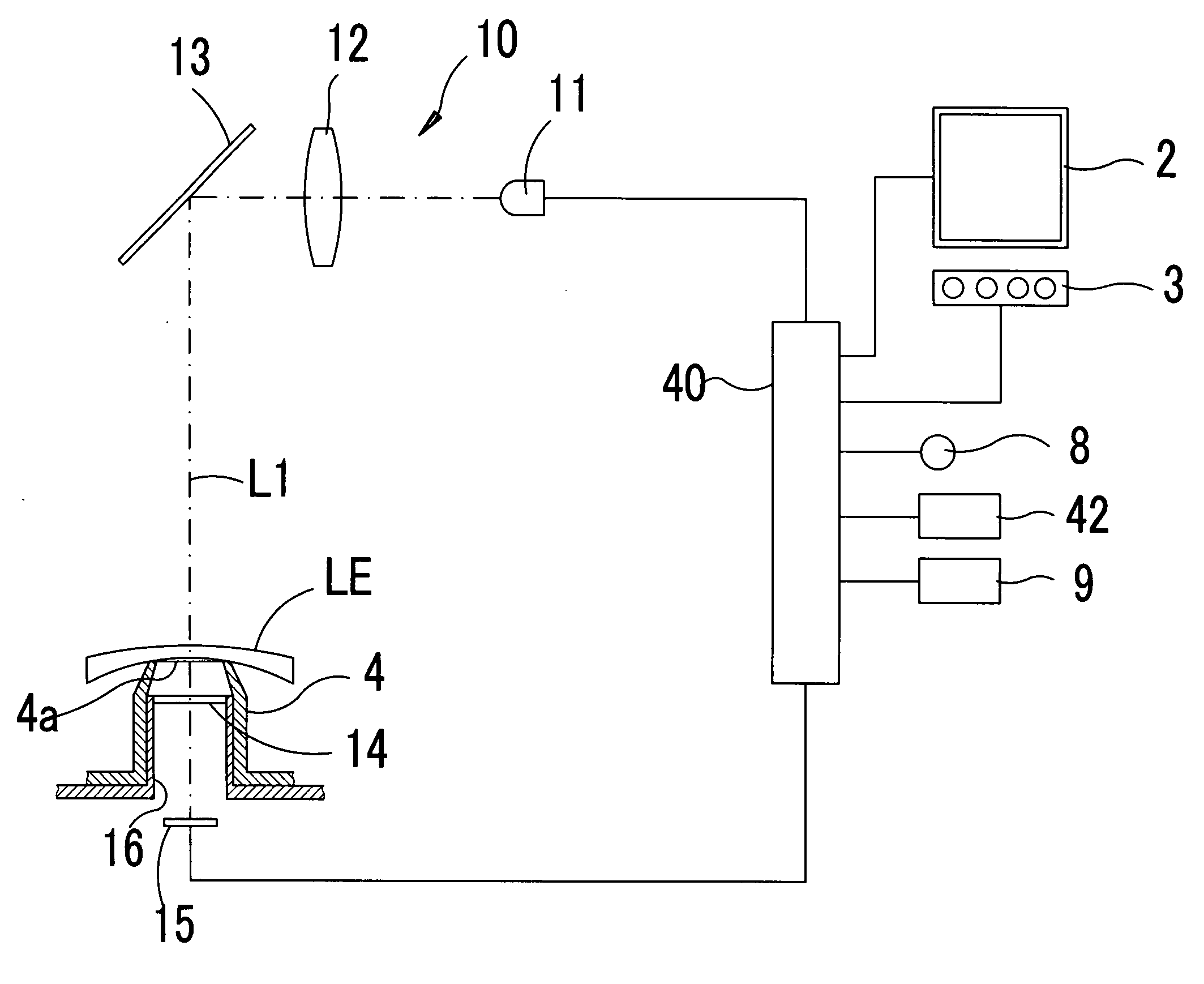
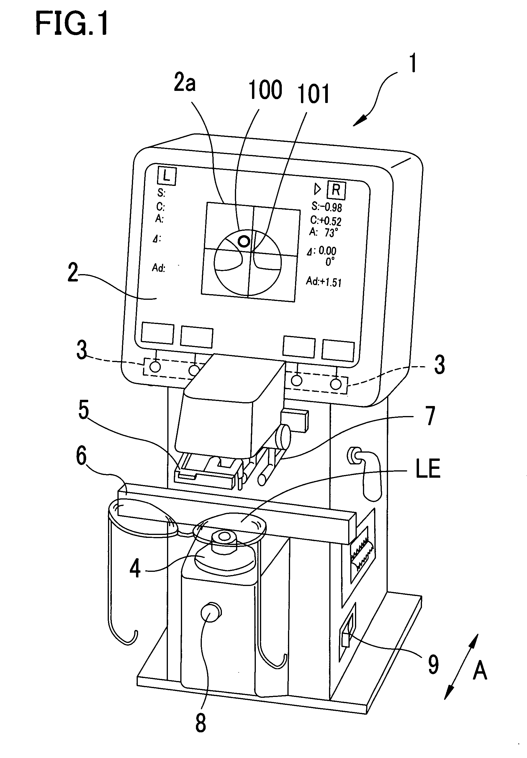
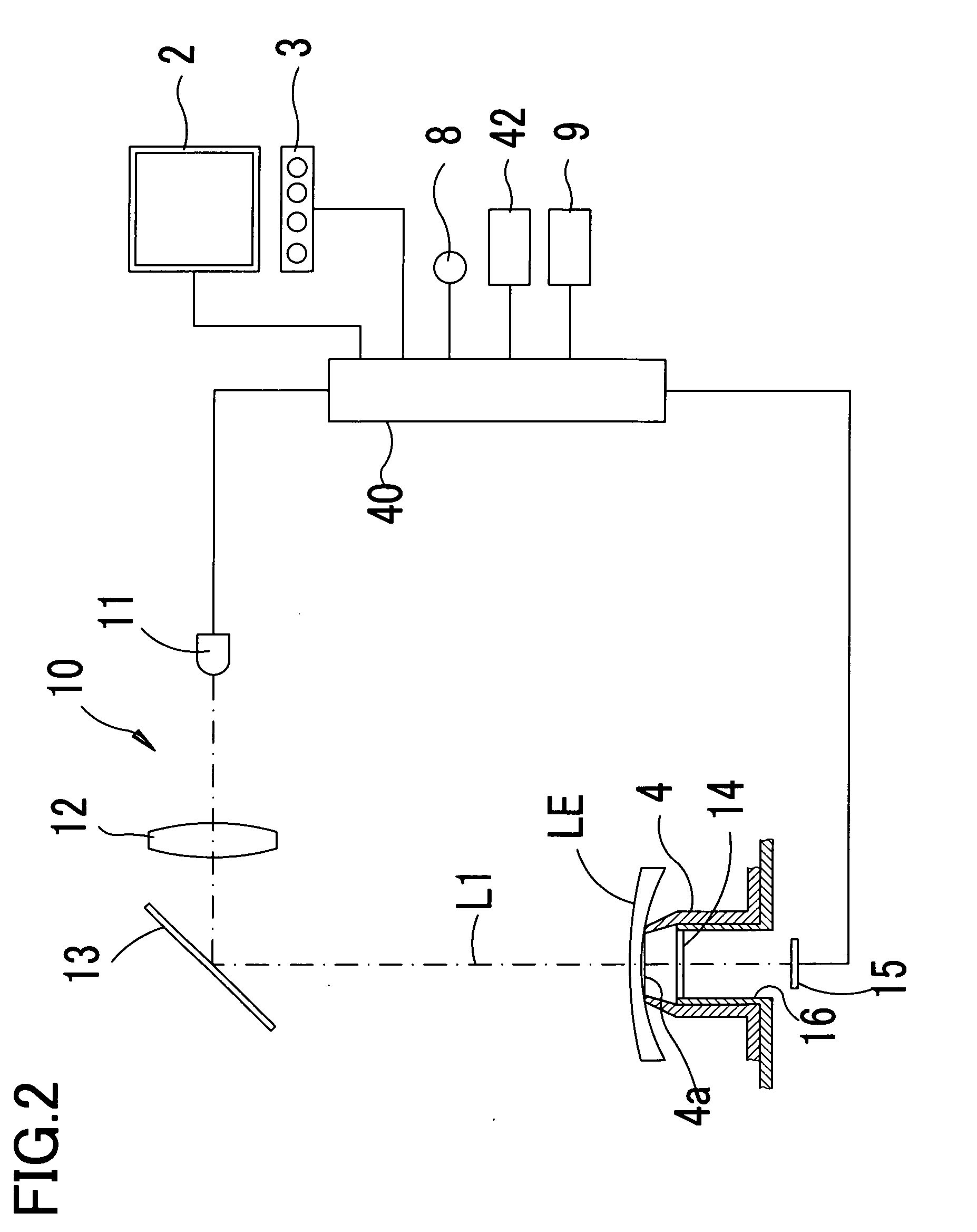
[0053]A preferred embodiment of the present invention will be described referring to the drawings. FIG. 1 is a schematic external view of a lens meter in the embodiment of the present invention.

[0054]On a display 2 such as a liquid crystal display provided in an upper part of a main body 1 of the lens meter, information necessary for measurement, measurement results, and others are displayed. Further, with the press of a switch 3 corresponding to a switch display appearing on the display 2, a necessary command such as measurement mode switching and the like is input. A target lens LE to be measured is mounted on a nosepiece (a lens table) 4. A lens retainer 5 is moved down (toward the nosepiece 4) to stably hold the lens LE on the nosepiece 4. When the lens LE set in a spectacle frame is to be measured, a frame rest (a lens rest) 6 movable backward and forward (in a direction indicated by an arrow A) is brought into contact with lower edges (lower edges in a spectacle wearing state)...


PUM


Abstract

A lens meter for measuring optical characteristics of a lens to be measured includes a measurement optical system including a light source which projects a measurement light beam to the lens and a light receiving sensor which receives the measurement light beam having passed through the lens; an arithmetic part which obtains optical characteristic distribution of a predetermined measurement region of the lens based on a light reception result of the light receiving sensor; near-vision-portion determination means which determines whether a near vision portion of the lens is present in the measurement region based on the optical characteristic distribution in the measurement region; and detection means which detects presence of a non-optical region in addition to an optical region of the lens in the measurement region based on the light reception result of the light receiving sensor; the arithmetic part obtains additional power of the lens based on the optical characteristic distribution of the optical region in the measurement region when the near-vision-portion determination means does not determine the presence of the near vision portion in the measurement region and the detection means detects the presence of the non-optical region in the measurement region.

Description

TECHNICAL FIELD[0001]The present invention relates to a lens meter for measuring optical characteristics of a lens.BACKGROUND ART[0002]There is a lens meter arranged to project a measurement light beam to a target lens to be measured, which is placed on a measurement optical axis, receive the measurement light beam having passed through the target lens by a light receiving sensor, and obtain optical characteristics of the target lens such as refractive power based on a light reception result of the sensor. There has also been proposed a lens meter arranged to obtain the optical characteristics at each of a plurality of measurement positions (measurement points) in a predetermined measurement region of the target lens, that is, optical characteristic distribution in the measurement region. Such a lens meter makes it easy to measure a near vision portion of a progressive lens based on the optical characteristic distribution in the measurement region.[0003]Recently, fashionability of s...

Claims


Application Information

Patent Timeline
Patent Type & Authority Applications(United States)
IPC IPC(8): G01M11/02
CPCG01M11/0264G01M11/0235G01N21/17G01N2021/9583
Inventor KAJINO, TADASHI
Owner NIDEK CO LTD
Features
  • R&D
  • Intellectual Property
  • Life Sciences
  • Materials
  • Tech Scout
  • Unparalleled Data Quality
  • Higher Quality Content
  • 60% Fewer Hallucinations
Learn More