Counter multi-failure system and common link terminal device used therein

a multi-failure system and terminal device technology, applied in data switching networks, frequency-division multiplexes, instruments, etc., can solve problems such as failure to recover communication, interference of auxiliary monitor frames, and large loops (super loops)

Inactive Publication Date: 2009-01-22
ALAXALA NETWORKS
View PDF3 Cites 15 Cited by
  • Summary
  • Abstract
  • Description
  • Claims
  • Application Information

AI Technical Summary

Benefits of technology

[0011]In a network of a multi-ring structure, even in a multi-failure state with a failure on a common link and another failure on a link other than the common link, there would be a demand for detecting the occurrence of multiple failures and enable continuous communication without increasing the number of relay devices as passing points of a monitor frame.
[0014]In the counter multi-failure system according to one aspect of the invention, upon detection of the occurrence of multiple failures including a failure of the common link, the common link terminal device is controlled to stop transmission of the auxiliary monitor frame. The monitor device receives neither the monitor frame for the preset time period nor the auxiliary monitor frame and thereby cancels the blocking of the specific port. Cancellation of the blocking of the specific port in this manner enables continuous communication without increasing the number of relay devices as the passing points of the monitor frame. This arrangement allows continuous communication even in the occurrence of multiple failures in the communication network of the multi-ring structure.
[0020]In the counter multi-failure system of this application, even in the event of detection of multiple failures, the multi-ring structure may allow continuous communication without cancelling the blocking of the specific port in the monitor device located on the second ring. In such cases, there is no need of stopping transmission of the auxiliary monitor frame.
[0022]Upon detection of the occurrence of multiple failures including a failure of the common link, the common link terminal device according to this aspect of the invention stops transmission of the auxiliary monitor frame to the monitor device. The monitor device does not receive the auxiliary monitor frame and may cancel the blocking of the specific port under a predetermined condition. Cancellation of the blocking of the specific port in this manner enables continuous communication without increasing the number of relay devices as the passing points of the monitor frame. This arrangement allows continuous communication even in the occurrence of multiple failures in the communication network of the multi-ring structure.
[0026]Even in the event of detection of multiple failures, the multi-ring structure may allow continuous communication without cancelling the blocking of the specific port in the monitor device located on the second ring. In such cases, there is no need of stopping transmission of the auxiliary monitor frame.

Problems solved by technology

In the multi-ring structure with a common link, however, in the event of a failure occurring on the common link, the interlinked rings may cause a large loop (super-loop).
In the prior art system of the former cited reference, however, in a multi-failure state with one failure on the common link and another failure on another link in the ring assigned to the working ring of monitoring the common link, the auxiliary monitor frame sent from the common link terminal device reaches the monitor device in the ring assigned to the non-working ring of monitoring the common link.
The reception of the auxiliary monitor frame interferes with release of the blocked port in the monitor device.
This leads to failed recovery of communication even in the presence of the physical connection.
In the prior art system of the latter cited reference, on the other hand, in a multi-failure state with one failure on the common link and another failure on another link in the ring assigned to the working ring of monitoring the common link, the monitor frame does not reach the monitor device in the ring assigned to the non-working ring of monitoring the common link.
The occurrence of each failure on the common link increases the number of relay devices as passing points of a monitor frame.
This causes the delay of the monitor frame and increases the potential for wasting the frame due to the convergence.

Method used


Image

  • Counter multi-failure system and common link terminal device used therein
  • Counter multi-failure system and common link terminal device used therein
  • Counter multi-failure system and common link terminal device used therein

Examples


first embodiment

A. First Embodiment

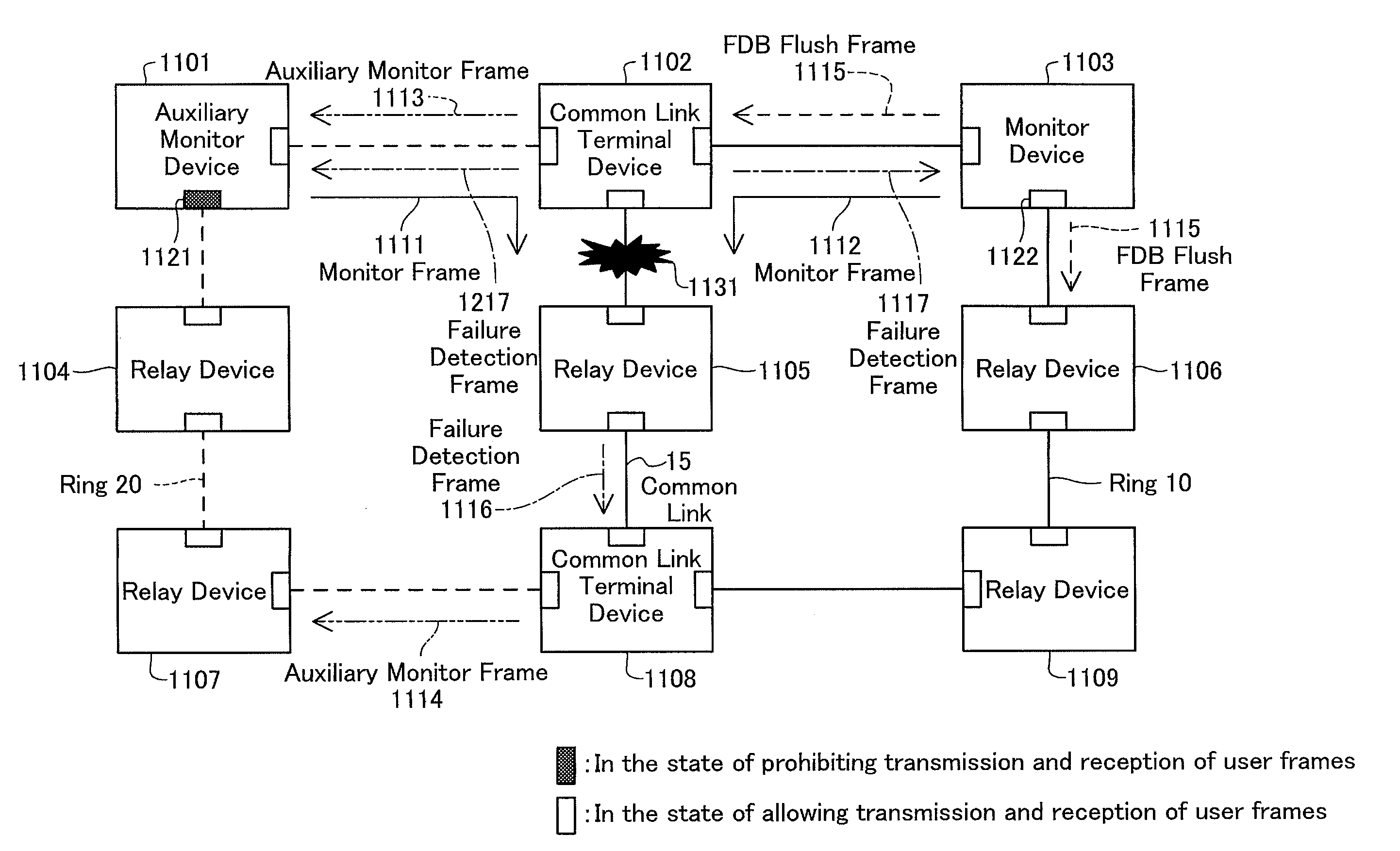
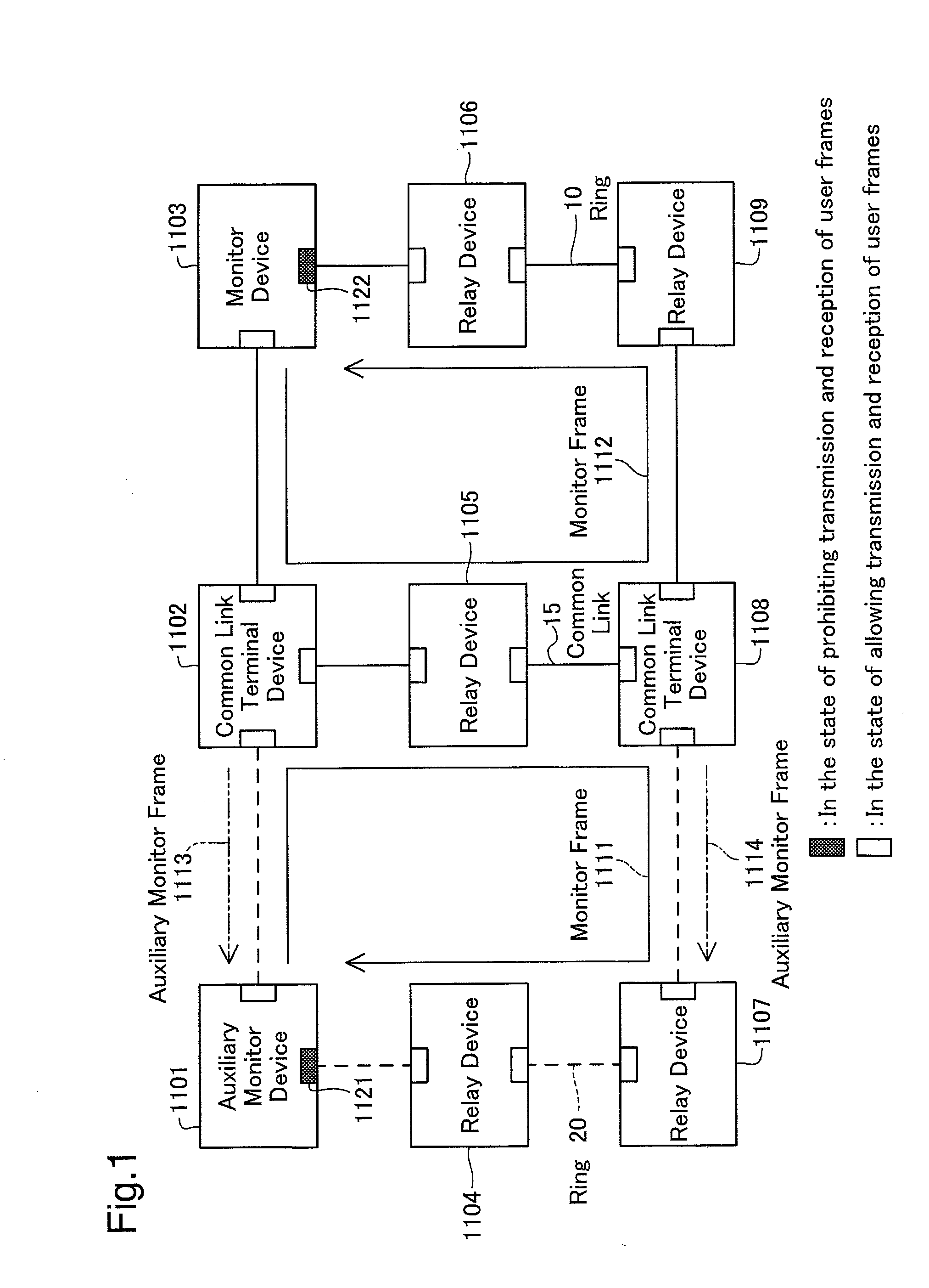
[0058]FIG. 1 is a block diagram showing an Ethernet communication network in a multi-ring structure according to a first embodiment of the invention. In the Ethernet communication network, a ring 10 includes a monitor device 1103, relay devices 1106 and 1109, a relay device 1105, and common link terminal devices 1102 and 1108. A ring 20 includes an auxiliary monitor device 1101, relay devices 1104 and 1107, the relay device 1105, and the common link terminal devices 1102 and 1108. IDs ‘10’ and ‘20’ are allocated respectively to the ring 10 and to the ring 20.

[0059]A link connecting the common link terminal device 1102 with the relay device 1105 and the common link terminal device 1108 is a common link 15 shared by the ring 10 and the ring 20.

[0060]The common link terminal devices 1102 and 1108 respectively send auxiliary monitor frames 1113 and 1114 to the auxiliary monitor device 1101 in the ring 20. This assigns the ring 20 to a non-working ring of monitoring th...

second embodiment

B. Second Embodiment

[0098]FIG. 9 is a block diagram showing an Ethernet communication network in a multi-ring structure according to a second embodiment of the invention. A ring 10 includes a monitor device 2107, a relay device 2106, and common link terminal devices 2103 and 2110. A ring 20 includes an auxiliary monitor device 2105, relay devices 2102 and 2109, the relay device 2106, and the common link terminal devices 2103 and 2110. A ring 30 includes an auxiliary monitor device 2104, relay devices 2101 and 2108, the relay device 2106, and the common link terminal devices 2103 and 2110. IDs ‘10’, ‘20’, and ‘30’ are allocated respectively to the ring 10, to the ring 20, and to the ring 30.

[0099]A link connecting the common link terminal device 2103 with the relay device 2106 and the common link terminal device 2110 is a common link shared by the three rings 10, 20, and 30.

[0100]In the communication network of the second embodiment, each of the common link terminal devices 2103 and ...

third embodiment

C. Third Embodiment

[0120]FIG. 12 is a block diagram showing an Ethernet communication network in a multi-ring structure according to a third embodiment of the invention. The communication network of the third embodiment has multiple common links. A ring 10 includes a monitor device 3103, a relay device 3106, and common link terminal devices 3102, 3105, 3108, 3109, 3142, and 3143. A ring 20 includes an auxiliary monitor device 3101, a relay device 3104, and the common link terminal devices 3102 and 3105. A ring 30 includes an auxiliary monitor device 3107, a relay device 3141, and the common link terminal devices 3108 and 3142. A ring 40 includes an auxiliary monitor device 3110, a relay device 3144, and the common link terminal devices 3109 and 3143. IDs ‘10’, ‘20’, ‘30’, and ‘40’ are allocated respectively to the ring 10, to the ring 20, to the ring 30, and to the ring 40.

[0121]A link between the common link terminal devices 3102 and 3105 is a common link shared by the rings 10 and...


PUM


Abstract

In a communication network including a monitor device, a relay device, and a common link terminal device, in response to detection of a link failure in a ring, each device sends a failure detection frame to the ring and causes link failure information to reach the common link terminal device. The common link terminal device generates a link failure information management database, performs a multi-failure detection process, and stops transmission of an auxiliary monitor frame upon detection of multiple failures.

Description

BACKGROUND OF THE INVENTION[0001]1. Field of the Invention[0002]The present invention relates to a technique of dealing with multiple link failures occurring in a communication network.[0003]2. Description of the Related Art[0004]A transmission control procedure called a ring protocol is generally adopted in topology of a ring structure (hereafter referred to as ring topology) in an Ethernet (registered trademark) communication network. The ring protocol is a layer 2 network redundant protocol. Multiple devices relaying user frames in a ring (hereafter these devices are referred to as relay devices) are interlinked in the ring structure. At least one of the relay devices is assigned to a device sending a frame (monitor frame) for checking the state of the ring (hereafter this device is referred to as monitor device). This arrangement of the ring protocol continuously monitors the state of the ring and controls ports of the respective devices to detect the occurrence of any failure a...

Claims


Application Information

Patent Timeline
Patent Type & Authority Applications(United States)
IPC IPC(8): H04L12/26
CPCH04L12/437H04L43/0811H04L41/069H04B1/74
Inventor YOSHIMARU, TAKEHIRO
Owner ALAXALA NETWORKS
Why Eureka
Try Eureka