Geared motor

a geared motor and gear technology, applied in the direction of gearing, slip coupling, coupling, etc., can solve the problems of unstable rotation of the output shaft with respect to the gear member, and the inability to reliably transmit the rotation force from the gear member to the output shaft, etc., to achieve stable rotation, easy to wear away, and reliable transmission

Inactive Publication Date: 2015-08-04
COPAL CO LTD
View PDF7 Cites 8 Cited by
  • Summary
  • Abstract
  • Description
  • Claims
  • Application Information

AI Technical Summary

Benefits of technology

[0007]Accordingly, an object of the present invention is to provide a geared motor capable of reliably transmitting a rotating force while avoiding unstable rotation.
[0009]In the geared motor according to the aspect of the present invention, the first insertion portion of the second gear unit made of a resin is inserted in the cylindrical portion of the first gear unit made of a resin, and the inner peripheral surface of the cylindrical portion is pressed by the pressing portions on the first insertion portion. Thus, the second gear unit is lightly press-fitted to the first gear unit in the axial direction. When the first gear unit or the second gear unit is locked, the pressing portions on the first insertion portion of the second gear unit move along the inner peripheral surface of the cylindrical portion of the first gear unit in the circumferential direction. The pressing portions on the first insertion portion move along the projecting-and-recessed portion of the inner peripheral surface of the cylindrical portion, so that torque is not transmitted between the first gear unit and the second gear unit. Thus, according to the aspect of the present invention, the pressing portions on the first insertion portion of the second gear unit move along the projecting-and-recessed portion of the inner peripheral surface of the first gear unit to stop the transmission of torque. Since the inner peripheral surface of the cylindrical portion of the first gear unit is pressed by the pressing portions on the first insertion portion of the second gear unit, the rotating force can be reliably transmitted between the first gear unit and the second gear unit. When viewed in the axial direction, the projecting-and-recessed portion of the inner peripheral surface of the cylindrical portion of the first gear unit is formed over the entire circumference, and the pressing portions on the first insertion portion of the second gear unit are evenly arranged in the circumferential direction. Therefore, rattling of the second gear unit with respect to the first gear unit can be suppressed and rotation of the second gear unit with respect to the first gear unit can be stabilized.
[0011]In this geared motor, the second gear unit further includes the second insertion portion that is inserted in the center hole in the first gear unit, and the engagement projection, which is engaged with the engagement recess in the wall surface of the center hole in the axial direction, is provided on the outer peripheral surface of the second insertion portion. Thus, the engagement projection of the second insertion portion of the second gear unit is placed in the engagement recess in the center hole of the first gear unit. Therefore, when a force is applied to the first gear unit or the second gear unit in the axial direction, the engagement projection of the second gear unit contacts a wall surface of the engagement recess in the first gear unit. Thus, movement of the second gear unit with respect to the first gear unit in the axial direction is regulated, and the second gear unit is reliably prevented from being pulled out from the first gear unit.
[0013]In this geared motor, each of the pressing portions provided on the outer peripheral surface of the first insertion portion of the second gear unit is the projection having a curved end, and the wall surface of each of the recesses in the inner peripheral surface of the cylindrical portion of the first gear unit is gently curved such that the two reference lines form an obtuse angle. If, for example, the radius of curvature of the wall surface of each of the recesses in the inner peripheral surface of the cylindrical portion of the first gear unit is reduced so that the two reference lines form an acute angle, the second gear unit is not easily pulled out from the first gear unit since the pressing portions of the second gear unit fit into the recesses in the inner peripheral surface of the first gear unit and press the inner peripheral surface of the first gear unit. However, in a locked state, the pressing force applied by the pressing portions of the second gear unit tends to concentrate at projections on the inner peripheral surface of the first gear unit. Since the pressing portions of the second gear unit try to move in the circumferential direction while pressing the projections on the inner peripheral surface of the first gear unit, the projections on the inner peripheral surface of the first gear unit wear away. In contrast, according to the aspect of the present invention, the pressing portions of the second gear unit have curved ends, and the wall surfaces of the recesses in the first gear unit are gently curved. Therefore, the pressing force applied by the pressing portions of the second gear unit to the inner peripheral surface of the first gear unit in the circumferential direction is small, and the pressing portions of the second gear unit move smoothly along the wall surfaces of the recesses in the first gear unit. Therefore, the projections on the inner peripheral surface of the first gear unit do not easily wear away. Thus, according to the aspect of the present invention, the pressing portions of the second gear unit can be moved smoothly along the inner peripheral surface of the first gear unit in the circumferential direction in the locked state, and wear of the projections on the inner peripheral surface of the first gear unit can be reduced.
[0014]According to the present invention, unstable rotation can be avoided and a rotating force can be reliably transmitted.

Problems solved by technology

As a result, stability of rotation of the output shaft with respect to the gear member is gradually reduced, and there is a risk that the rotating force cannot be reliably transmitted from the gear member to the output shaft.

Method used


Image

  • Geared motor
  • Geared motor
  • Geared motor

Examples


Embodiment Construction

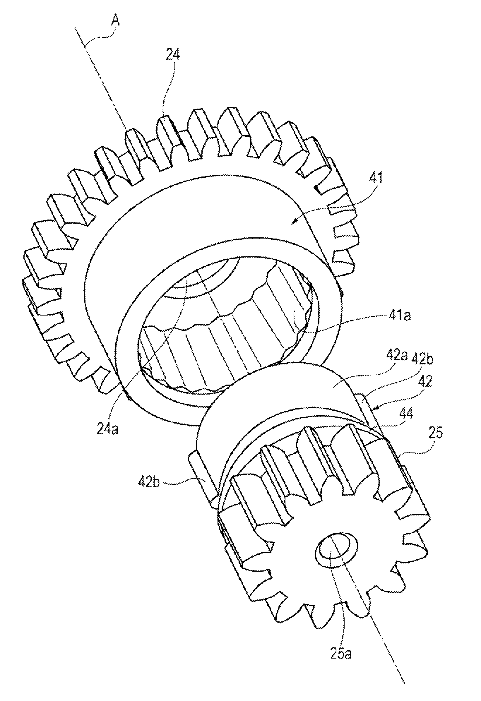
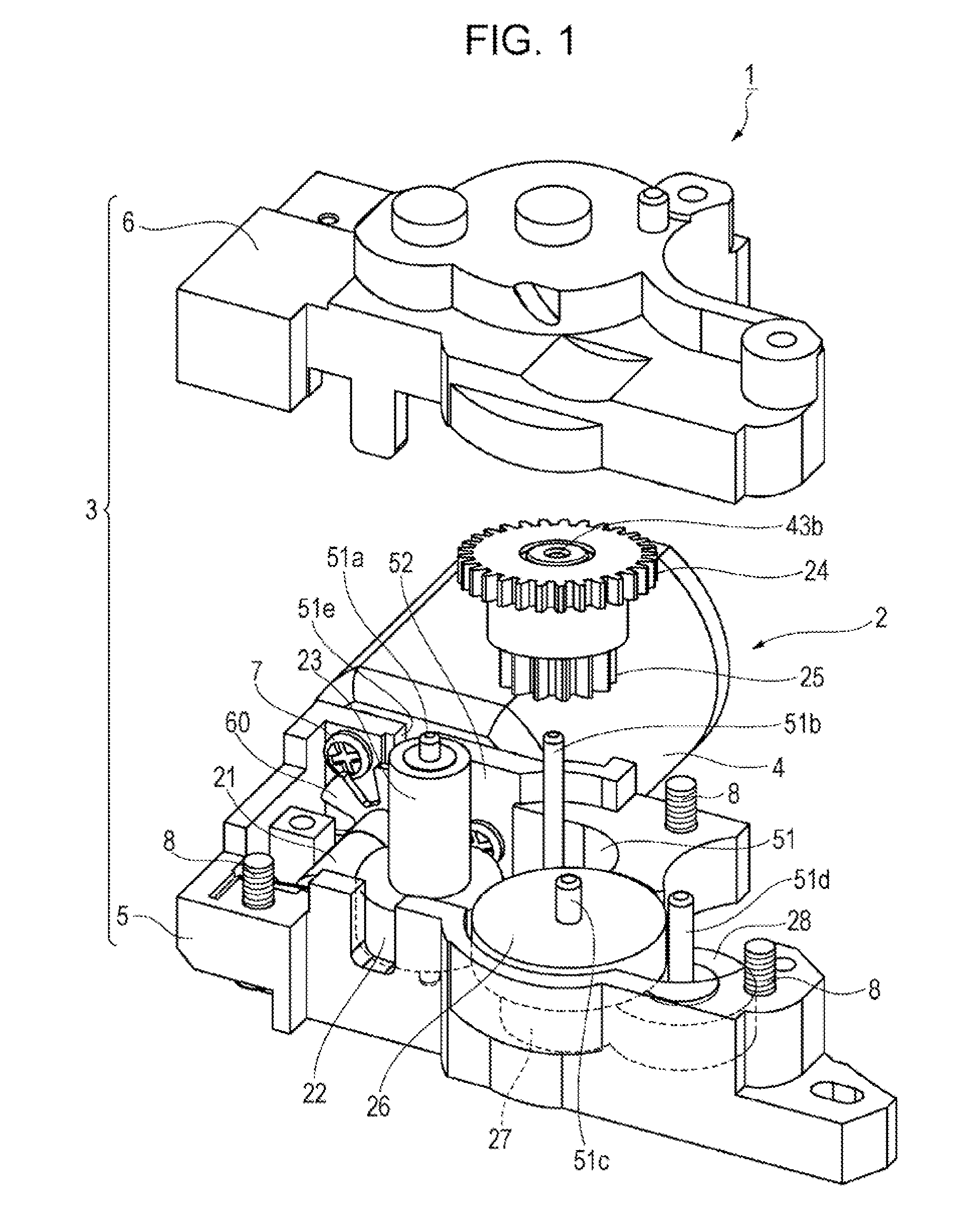
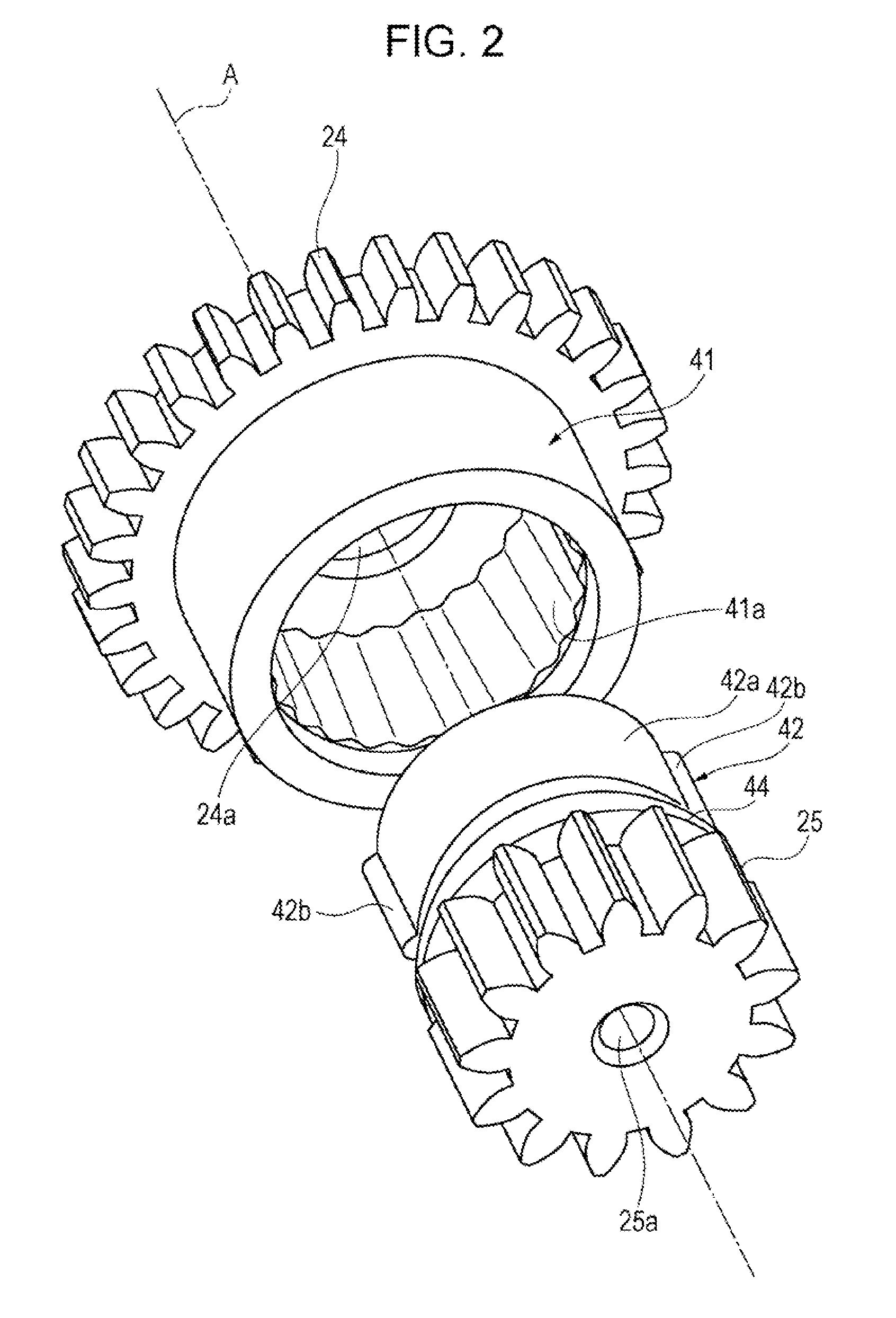
[0023]A geared motor according to a preferred embodiment of the present invention will be described in detail with reference to the drawings.

[0024]A geared motor 1 illustrated in FIG. 1 is mounted in an electronic apparatus, such as an amusement apparatus, an audio-visual apparatus, a medical apparatus, or a camera, and is used as a small unit in a mechanical section of the electronic apparatus. The geared motor 1 reduces a speed of rotation of a DC motor 4 with a gear train 2 and outputs the rotation to the outside. The geared motor 1 includes a gear box 3 made of a resin that houses the gear train 2, which includes a plurality of gears that constitute a speed reduction mechanism. The gear box 3 includes a gear holder 5, and the DC motor 4 is fastened with screws to a side wall of the gear holder 5. The gear box 3 includes the gear holder 5, which is made of a resin and which has an accommodation recess 51 for accommodating the gear train 2, and a gear cover 6, which is also made o...


PUM


Abstract

A geared motor reduces a speed of rotation of a DC motor with a gear train and outputs the rotation to the outside. The gear train includes a second gear including a cylindrical portion a third gear a first insertion portion that is inserted in the cylindrical portion the second gear. The second gear and the third gear are made of a resin material. A projecting-and-recessed portion is provided on an inner peripheral surface of the cylindrical portion of the second gear. The projecting-and-recessed portion extends continuously in a circumferential direction over the entire circumference of the inner peripheral surface of the cylindrical portion. Pressing portions are evenly arranged in the circumferential direction on an outer peripheral surface of the first insertion portion of the third gear. The pressing portions are configured enter recesses in the projecting-and-recessed portion and press wall surfaces of the recesses.

Description

CROSS REFERENCES TO RELATED APPLICATIONS[0001]The present invention contains subject matter related to Japanese Patent Application No. 2012-268498 filed in the Japan Patent Office on Dec. 7, 2012, the entire contents of which are incorporated herein by reference.BACKGROUND OF THE INVENTION[0002]1. Field of the Invention[0003]The present invention relates to a small geared motor mounted in a precision apparatus, such as an amusement apparatus, an audio-visual apparatus, a medical apparatus, or a camera.[0004]2. Description of the Related Art[0005]Japanese Unexamined Patent Application Publication No. 2012-62963 discloses a technology in this field. This document describes a reduction gear mechanism including a clutch that stops transmitting power between an output shaft and a gear member in case of overload. In this reduction gear mechanism, the gear member includes a shaft-receiving portion in which the output shaft is rotatably inserted and an outer cylindrical portion that surroun...

Claims


Application Information

Patent Timeline
Patent Type & Authority Patents(United States)
IPC IPC(8): H02K7/116F16D7/00F16H35/10F16H1/12F16H57/00F16H1/06F16H1/20F16D7/04
CPCF16H35/10F16D7/002F16H1/06F16D7/048Y10T74/19679F16D1/101F16H1/20H02K7/116
Inventor FUJISAWA, KEISUKE
Owner COPAL CO LTD
Why Eureka
Try Eureka