
Shock absorbing fabric structures

Active Publication Date: 2009-01-22
YKK CORP OF AMERICA
View PDF64 Cites 25 Cited by
  • Summary
  • Abstract
  • Description
  • Claims
  • Application Information

AI Technical Summary

Benefits of technology

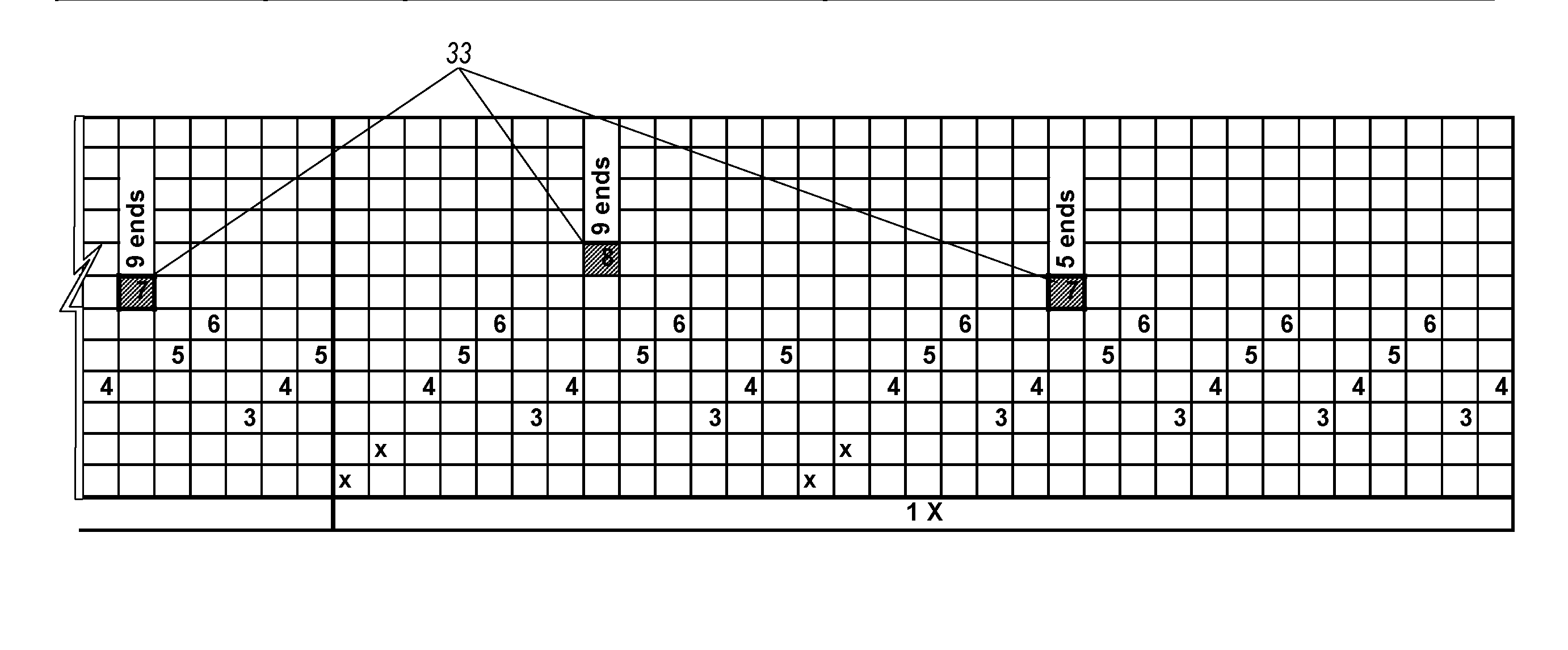
[0009]The elongation member can be made from elongation yarns, such as POY. In some embodiments, the webbing has a first connection segment, an expansion segment, and a second connection segment. In the first and second connection segments, the binder yarns can be interwoven with the ground yarns and the elongation yarns. In the expansion section, some of the lateral yarns can be interwoven with the elongation yarns to connect the elongation yarns with the sheath, and the binder yarns can be woven with the ground yarns of the sheath but not woven with the elongation yarns. Also in the expansion segment, the length of the elongation yarns can be shorter than the length of the sheath. Heat treatment can shrink the length of the elongation yarns in the expansion segment. In contrast, the yarns of the sheath do not substantially shrink from the heat treatment relative to the elongation member, and gather together in an accordion-like arrangement.

Problems solved by technology

People who are at elevated positions above a floor or other relatively lower surface can be at risk of falling and injury.
For example, workers and other personnel who have occupations that require them to be at elevated positions, such as on scaffolding, can be at risk of falling and injury.
With typical lanyards, however, the person's movement is stopped rather abruptly and the person is subjected to the shock force of the abrupt stop.
The relative length adjustment of the webbings is performed manually and is a significant disadvantage of existing lanyards.
Because conventional lanyards are made from two separate webbings that must be assembled together, manufacture of the lanyards requires costly and tedious assembly processes, such as inserting the POY webbing through the tubular-shaped webbing.
The manufacturing process is complicated by proper control and manual setting of the critical relative lengths of the two webbings.

Method used


Image

  • Shock absorbing fabric structures
  • Shock absorbing fabric structures
  • Shock absorbing fabric structures

Examples


Embodiment Construction

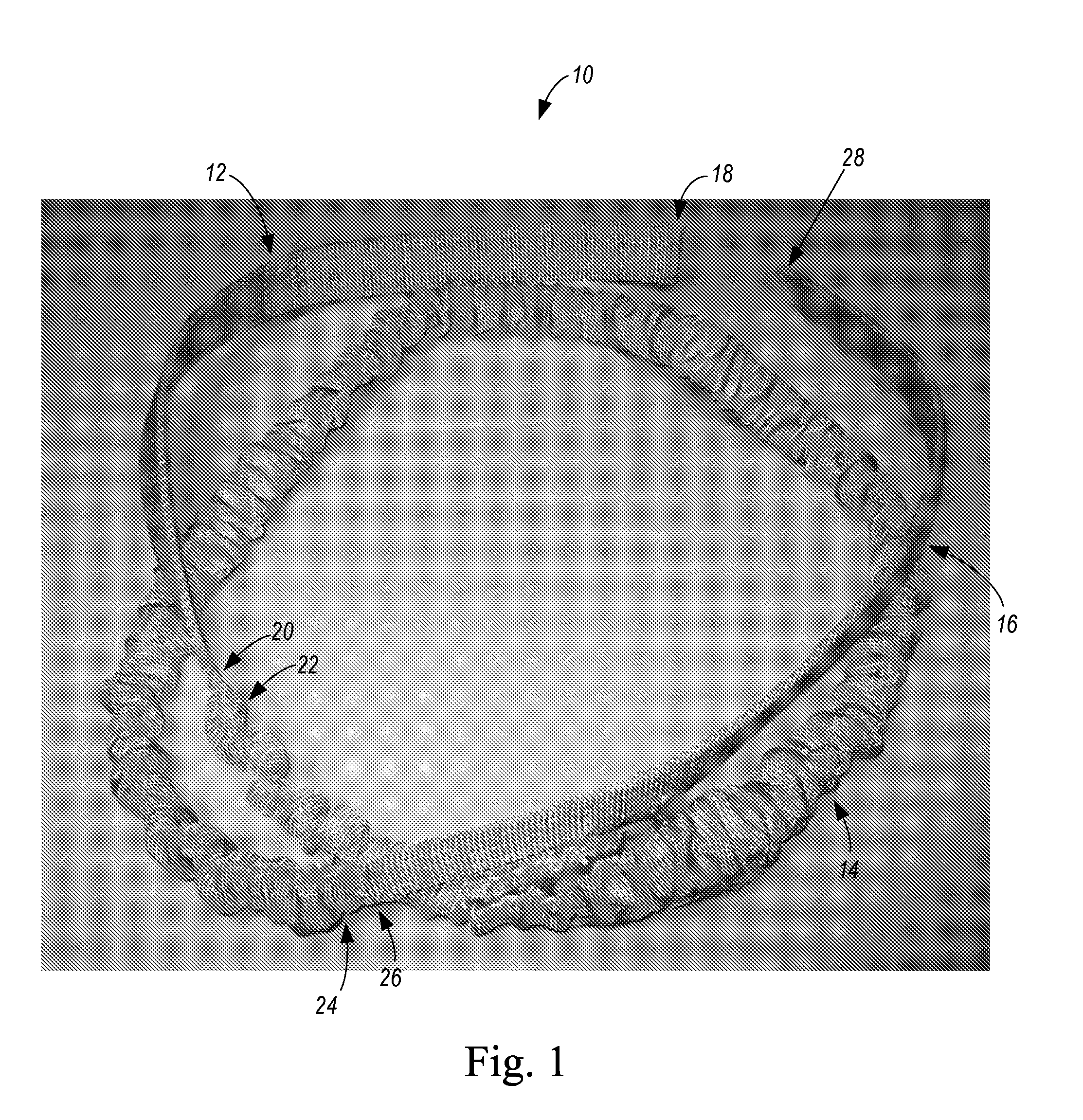
[0025]Certain embodiments of the invention provide fabric structures comprised of woven webbings 10. As shown in FIG. 1, the woven webbing 10 according to one embodiment comprises a first connection segment 12, an expansion segment 14, and a second connection segment 16. The first connection segment 12 includes a first end 18 and a second end 20. The expansion segment 14 includes a first end 22 and a second end 24. The second connection segment includes a first end 26 and a second end 28. In the embodiment of FIG. 1, the first end 22 of the expansion segment 14 is adjacent to the second end 20 of the first connection segment 12, and the first end 26 of the second connection segment 16 is adjacent to the second end 24 of the expansion section 14.

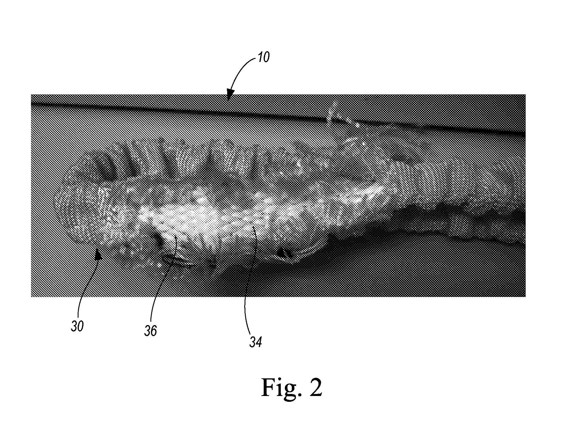
[0026]As shown in the embodiment of FIG. 2, the woven webbing 10 includes a plurality of elongation yarn bundles 34, each bundle comprising a plurality of elongation yarns 33, and a sheath 30, which is formed from a plurality of ground yarns ...


PUM

PropertyMeasurementUnit
Massaaaaaaaaaa
Lengthaaaaaaaaaa
Coloraaaaaaaaaa

Abstract

Fabric structures having two connection segments and an expansion segment between the two connection segments are provided. The fabric structure includes ground yarns that form a sheath, binder yarns, elongation yarns surrounded by the sheath, and lateral yarns. In the expansion segment, at least some of the lateral yarns are interwoven with the elongation yarns to connect the elongation yarns laterally with the sheath. Heat treatment of the expansion segment shrinks the length of the elongation yarns during manufacture. The sheath does not substantially shrink from the heat treatment relative to the elongation yarns and gathers together in an accordion-like arrangement. A tensile load applied to the fabric structure stretches the elongation yarns and unfolds the gathered sheath. The high strength sheath supports the tensile load when completely unfolded, while the elongation yarns absorbs energy as the fabric structure stretches or elongates.

Description

CROSS REFERENCE TO RELATED APPLICATIONS[0001]This application is a continuation-in-part of U.S. application Ser. No. 12 / 103,565 titled “Shock Absorbing Lanyards” filed Apr. 15, 2008, which is a continuation of U.S. application Ser. No. 10 / 790,394 titled “Shock Absorbing Lanyards” filed Mar. 1, 2004, both of which are incorporated herein by reference.BACKGROUND OF THE INVENTION[0002]People who are at elevated positions above a floor or other relatively lower surface can be at risk of falling and injury. For example, workers and other personnel who have occupations that require them to be at elevated positions, such as on scaffolding, can be at risk of falling and injury. Safety harnesses can be worn to stop a person's fall and prevent or reduce injury. Safety harnesses, such as a seat belt, also can be worn to secure the occupant of a vehicle in the event of a sudden stop or collision to reduce the risk of injury.[0003]Safety harnesses typically have a harness portion worn by the use...

Claims


Application Information

Patent Timeline
IPC IPC(8): D03D15/08D03D15/00D03D15/567D03D15/56
CPCA62B35/04B60R22/12D03D3/02D03D11/00D10B2401/063D03D15/00D03D15/04D03D15/08D10B2331/04D03D11/02Y10T442/3065Y10T442/3008D03D15/567D03D15/56D03D15/573D03D15/283
Inventor RUSSELL, TIMOTHY M.JENNIGS, JOHN E.
Owner YKK CORP OF AMERICA
Learn More