Power-Driven Hand Tool

a technology of hand tools and power, which is applied in the direction of metal-working holders, supporters, positioning apparatuses, etc., can solve the problems of not being able to withstand very high loads of the kind, the force produced by the known clamping device, and the inability to clamp electric tools with oscillating drives. to achieve the effect of facilitating the operation of releasing the securing element and close form-locking connection

Active Publication Date: 2009-01-22
C & E FEIN
View PDF10 Cites 85 Cited by
  • Summary
  • Abstract
  • Description
  • Claims
  • Application Information

AI Technical Summary

Benefits of technology

[0015]According to a further development of that embodiment, the securing element comprises a section with an inclined surface the whole extent of which engages the split chuck by a correspondingly adapted inner surface.
[0016]The section of the securing element that engages the split chuck can be given a substantially conical shape for this purpose.
[0017]This measure results in an even closer form-locking connection between the split chuck and the drive spindle so that a perfect form-locking connection is guaranteed in the clamping position.
[0018]According to another embodiment of the invention, a spring element is provided between the split chuck and the securing element.
[0019]This feature has the effect to facilitate the operation of releasing the securing element from the split chuck after transfer of the displacing device to the releasing position.
[0020]According to a further embodiment of the invention, the split chuck can be connected with the retaining section in form-locking engagement.

Problems solved by technology

However, it has been found that the forces that can be produced by the known clamping device, under the action of high clamping forces, will as a rule not suffice to withstand very high loads of the kind encountered especially in sawing tools and cutting tools with oscillatory drives.
However, the described clamping devices are designed exclusively for electric tools with rotary drives.
Electric tools with oscillating drives cannot be clamped.

Method used


Image

  • Power-Driven Hand Tool
  • Power-Driven Hand Tool

Examples


Embodiment Construction

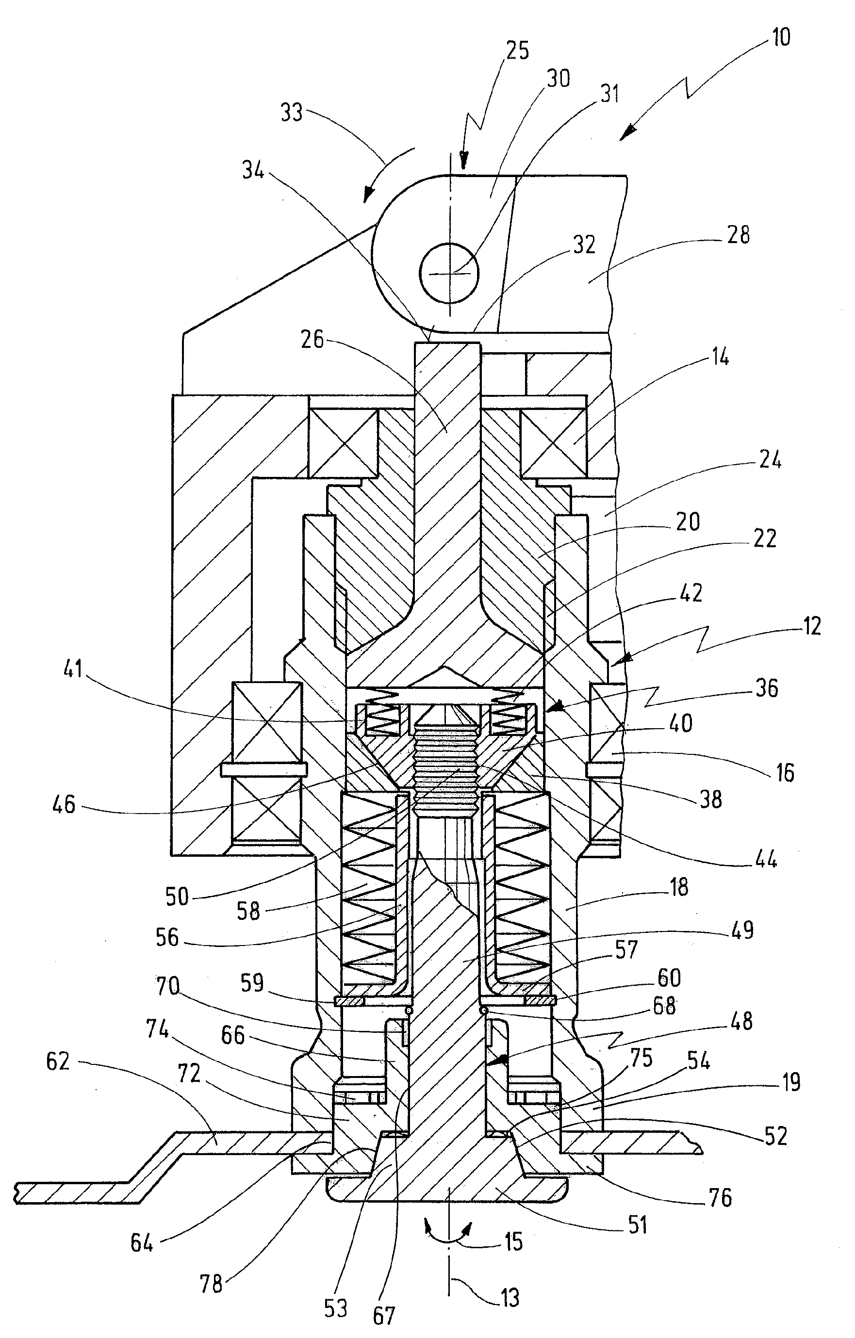
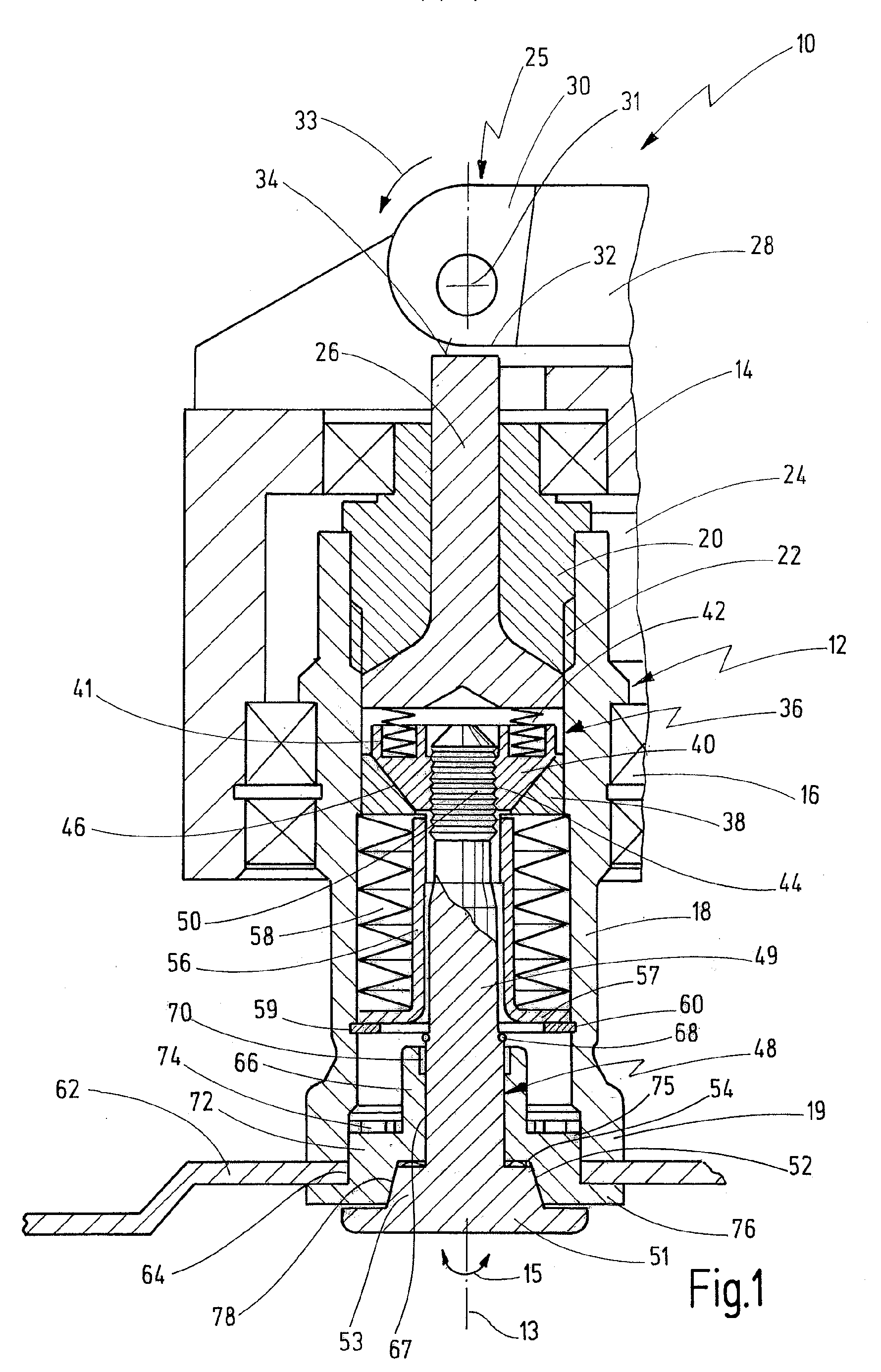
[0043]FIG. 1 shows a sectional view of the operating head area of a power-driven hand tool according to the invention, indicated generally by reference numeral 10. The hand tool 10 comprises a drive shaft 12 with a tool 62 mounted on its outer end using a clamping element that will be described in more detail hereafter.

[0044]The drive spindle 12 is driven to oscillate by an eccentric-driven oscillating fork 24, in a manner not shown in detail. As is indicated by double-arrow 15, the drive spindle 12 is moved about its longitudinal axis 13 at a high frequency of between approximately 10,000 and 25,000 oscillations per minute and a small oscillating angle of between approximately 0.5 and 7°.

[0045]Such hand tools 10, which are driven to oscillate, have recently come into use in many applications for carrying out special operations, including for example the operation of cutting out motor vehicle panes using an oscillating cutter, sawing using oscillating saw knives, grinding and many m...


PUM


Abstract

A power-driven hand tool comprises a drive spindle adapted to drive a tool, that can be driven to oscillate about its longitudinal axis, which tool can be fixed on a retaining section of the dive spindle by a securing element, and further comprises a displacing device that serves to displace the securing element between a releasing position in which the securing element can be released from the drive spindle and a clamping position in which the securing element is clamped on the retaining section by a spring element, the securing element comprising a clamping shaft adapted to be inserted into the securing element, which is axially fixed in the drive spindle for clamping the tool in the clamping position, and which can be detached in the releasing position. For clamping of the tool a split chuck is provided which is clamped on the retaining section by the securing element in the clamped position and is connected with the retaining section in form-locking engagement.

Description

BACKGROUND OF THE INVENTION[0001]The present invention relates to a power-driven hand tool having a motor-operated drive spindle, adapted to drive a tool which can be fixed on a retaining section of the drive spindle by a securing element, comprising a displacing device that serves to displace the securing element between a releasing position in which the securing element can be released from the drive spindle and a clamping position in which the securing element is clamped on the retaining section by a spring element, the securing element comprising a clamping shaft adapted to be inserted into the securing element, which shaft is axially fixed in the drive shaft in the clamping position, for clamping the tool, and can be detached in the releasing position.[0002]A power-driven hand tool of that kind is known from U.S. Pat. No. 7,344,435 which is fully incorporated by reference herewith.[0003]In the case of the known hand tool, a securing element can be introduced into the drive spin...

Claims


Application Information

Patent Timeline
Patent Type & Authority Applications(United States)
IPC IPC(8): B24B23/02B24B45/00
CPCB24B45/006B24B23/022
Inventor BLICKLE, JUERGENFRUEH, UWE
Owner C & E FEIN
Why Eureka
Try Eureka