
Method and apparatus for managing virtual ports on storage systems

a storage system and virtual port technology, applied in the field of storage systems, can solve the problems of increasing security risks, limiting the flexibility of connection between physical servers and storage systems, and the power consumed by servers in some data centers becoming a significant issu

Inactive Publication Date: 2009-01-22
HITACHI LTD
View PDF7 Cites 153 Cited by
  • Summary
  • Abstract
  • Description
  • Claims
  • Application Information

AI Technical Summary

Benefits of technology

The invention provides ways to manage virtual ports on storage systems so that they can ensure that servers and storage systems are always connected. This means that special software doesn't need to be installed on the servers. The invention also allows for load balancing between physical ports on the storage systems, and enables remote migration of virtual machines by using and transferring virtual ports. These features can be useful for those working in the field of storage systems.

Problems solved by technology

Recently, the amount of power consumed by servers in some data centers is becoming a significant issue.
Therefore, any volumes used by the virtual machines need to be able to be shared between the source server and the destination server, which limits flexibility of connection among physical servers and storage systems, and increases security risks.
However, to utilize conventional multipathing technology, specialized software is required to be installed on the servers, and conventional multipathing solutions do not address the use of or failover of virtual ports.
Although virtual machine software typically has a function to facilitate migration of a virtual machine to another server upon a failure at the first server (server clustering), virtual machine software does not meet requirements for disaster recovery because the storages still need to be shared among the servers, and the virtual machine needs to be able to access the storage volumes that it was using prior to migration, as mentioned above.

Method used


Image

  • Method and apparatus for managing virtual ports on storage systems
  • Method and apparatus for managing virtual ports on storage systems
  • Method and apparatus for managing virtual ports on storage systems

Examples


first embodiment

tion

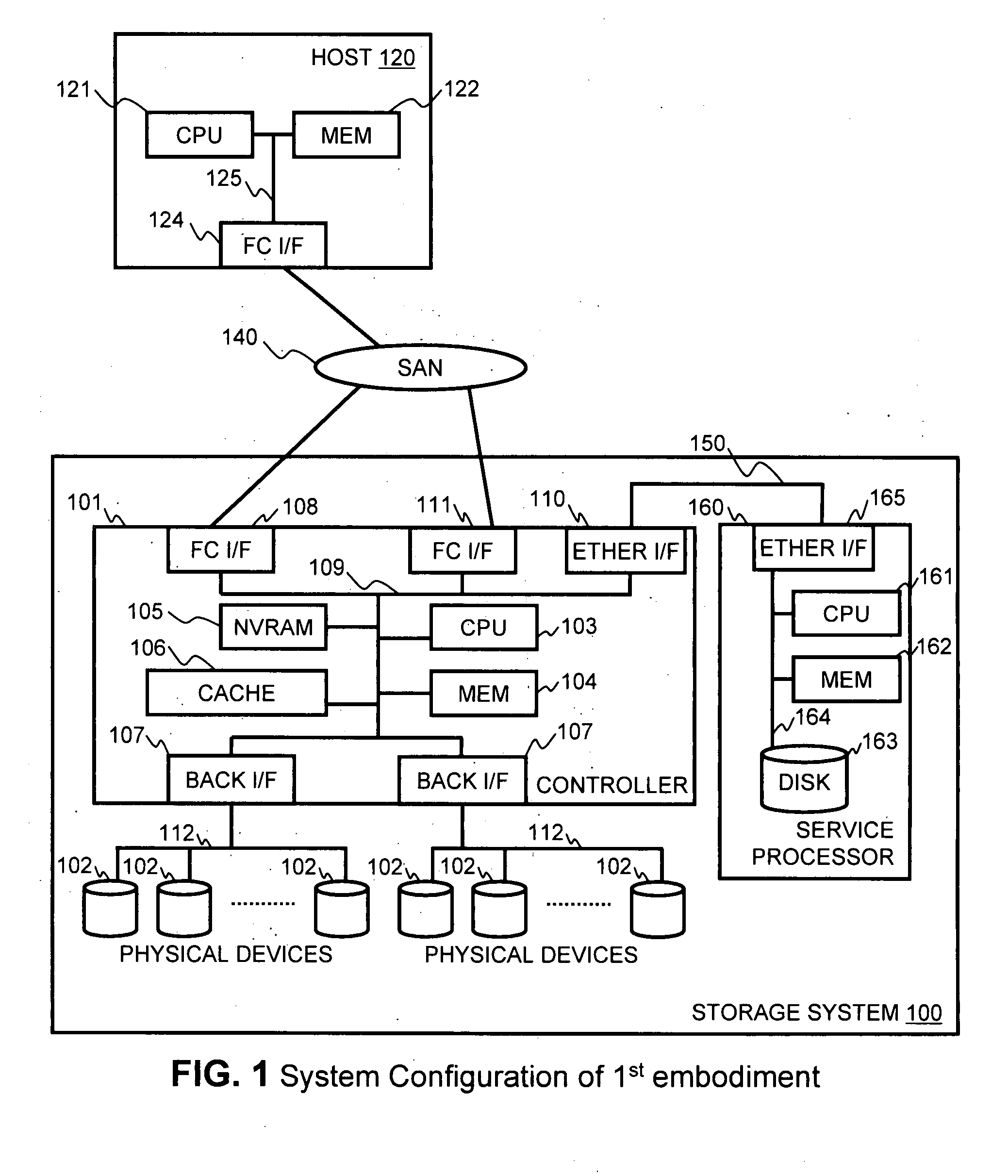
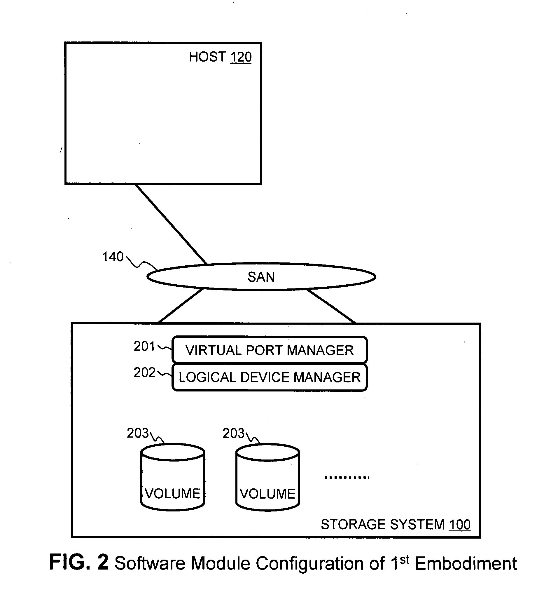
[0040]FIG. 1 illustrates an example of a hardware architecture of the information system of the first embodiment of the invention. In the information system illustrated in FIG. 1, a storage system 100 is connected for communication with one or more host computers 120 via a network 140, such as a Fibre Channel (FC) SAN (Storage Area Network). Storage system 100 includes a storage controller 101 in communication with one or more physical storage devices 102. Controller 101 includes a CPU 103, a memory 104, a NVRAM (non-volatile random access memory) 105, a cache memory 106, one or more backend interfaces 107, a plurality of front end interfaces 108, 111, and at least one Ethernet or LAN (local area network) interface 110. These components are connected to each other via an internal bus 109, or the like. When network 140 is an FC SAN, front end interfaces 108, 111 are FC interfaces, such as physical ports, each having its own physical WWN (World Wide Name). Controller 101 is able t...

second embodiment

ion

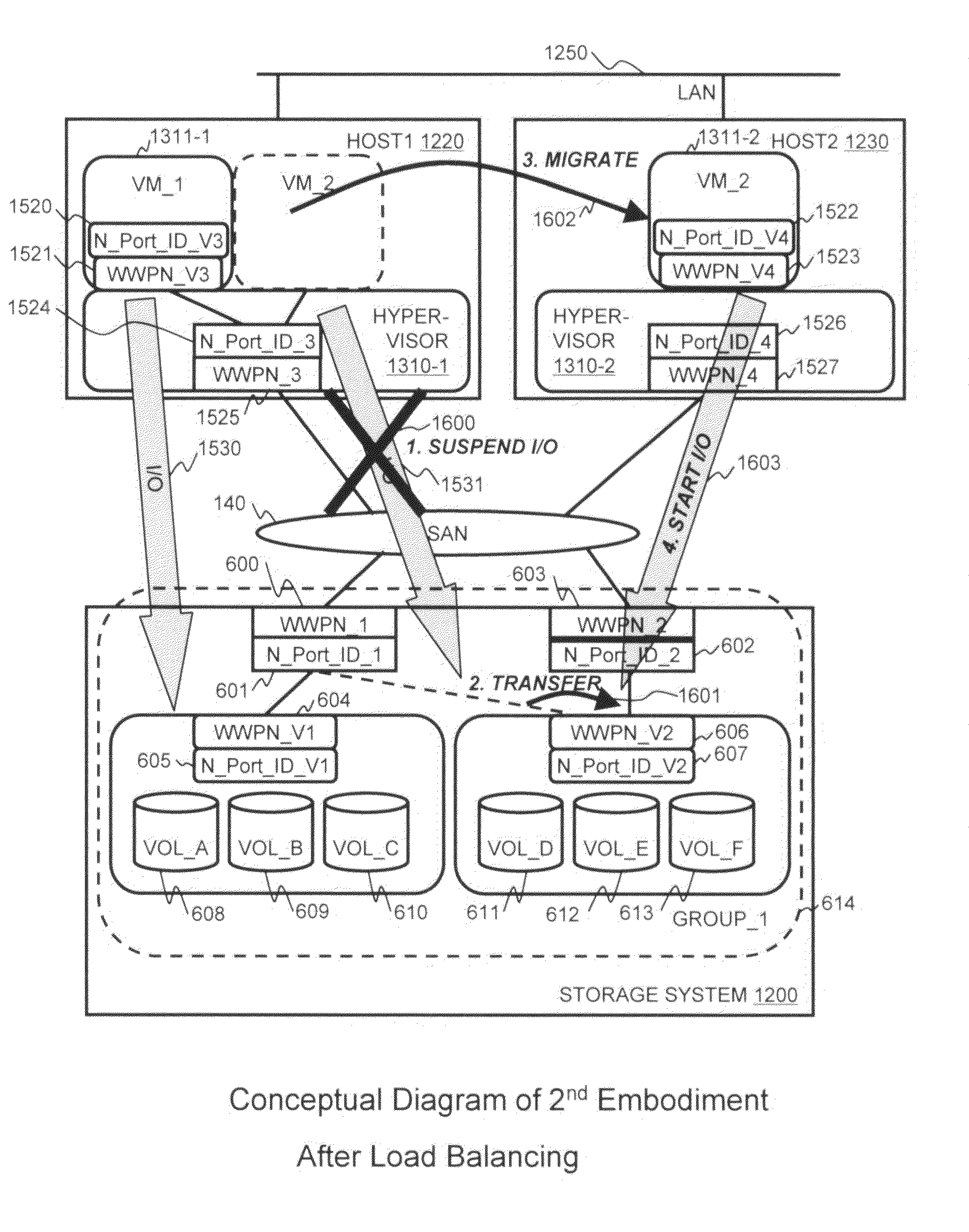
[0111]FIG. 12 illustrates an example of an information system which implements a second embodiment of the invention. A storage system 1200 includes the same components as the storage system 100 described above with respect to FIG. 1 for the first embodiments. Accordingly, those components do not need to be described again here.

[0112]Storage system 1200 is operably in communication with at least two host computers 1220 and 1230 in the information system of the second embodiments. Each host 1220 and 1230 comprises at least a CPU 1221, a memory 1222, an Ethernet interface 1223, and a FC interface 1224. These components are operably connected to each other via an internal bus 1225. Each host 1220 and 1230 is operably connected for communication to storage system 1200 through the FC interface 1224 via SAN 140. Also, hosts 1220 and 1230 are operably connected for communication to each other through Ethernet interface 1223 via LAN 1250.

[0113]Software Modules

[0114]As illustrated in FIG. ...

third embodiment

tion

[0136]FIG. 19 illustrates an example of an information system that implements a third embodiment of the invention. In this embodiment, a local storage system 1900 is operably connected for communication with a remote storage system 1901. Local storage system 1900 and remote storage system 1901 can include the same hardware components as storage system 100 described above in FIG. 1. However, local storage system 1900 may be connected to remote storage system 1901 via one of the FC interfaces through a remote copy link 1902. Remote copy link 1902 is typically composed of a WAN (Wide Area Network) and a Fibre Channel to Internet Protocol (FC-IP) converter such as an extender.

[0137]At least two hosts 1903 and 1904 exist in the system of the third embodiment, although more may exist at each location. A local host computer 1903 is in communication with local storage system 1900 via a local SAN 1905. A remote host computer 1904 is in communication with remote storage system 1901 via a ...


PUM


Abstract

A storage system is configured to create and manage virtual ports on physical ports. The storage system can transfer associations between virtual ports and physical ports when a failure occurs in a physical port or a link connected to the physical port so that a host can access volumes under the virtual ports through another physical port. The storage system can also change associations between virtual ports and physical ports by taking into account the relative loads on the physical ports. When a virtual machine is migrated from one host computer to another, the loads on the physical ports in the storage system can be used to determine whether load balancing should take place. Additionally, the storage system can transfer virtual ports to a remote storage system that will take over the virtual ports, so that a virtual machine can be migrated to remote location.

Description

BACKGROUND OF THE INVENTION[0001]1. Field of the Invention[0002]The present invention relates generally to storage systems that store data.[0003]2. Description of Related Art[0004]Recently, the amount of power consumed by servers in some data centers is becoming a significant issue. One possible solution for this problem is server consolidation using virtual machine software. Virtual machine software is able to provide multiple virtual server environments (i.e., virtual machines or VMs) on a single server hardware (or a physical server), and thereby enable the physical single server to run multiple operating systems (OSs). What is more, virtual machines that are in operation on virtual machine software are able to be migrated to another physical server for the purpose of load balancing between physical servers, clustering in preparation for server hardware failure, and for other purposes. However, when a virtual machine is migrated from a current physical server (i.e., a source serv...

Claims


Application Information

Patent Timeline
Patent Type & Authority Applications(United States)
IPC IPC(8): G06F9/46G06F12/00
CPCG06F3/0607G06F3/0664G06F9/5077G06F9/4856G06F9/505G06F3/067
Inventor HARA, JUNICHIKANO, YOSHIKI
Owner HITACHI LTD
Learn More