Variable valve timing control apparatus with supplementary oil pump

a technology of variable valve timing and control apparatus, which is applied in the direction of electrical control, engine starters, instruments, etc., can solve the problems of engine start-up delay, inability to control the opening and closing timing of valves, and inability to achieve reliable lock conditions

Inactive Publication Date: 2009-01-29
AISIN SEIKI KK
View PDF4 Cites 39 Cited by
  • Summary
  • Abstract
  • Description
  • Claims
  • Application Information

AI Technical Summary

Benefits of technology

[0010]According to an aspect of the present invention, a variable valve timing control apparatus includes: a drive-side rotational member rotatable in synchronization with a crankshaft; a driven-side rotational member positioned coaxially with the drive-side rotational member and being rotatable integrally with a camshaft; at least one fluid pressure chamber defined at least one of the drive-side rotational member and the driven-side rotational member; at least one vane diving the fluid pressure chamber into an advanced angle chamber and a retarded angle chamber; a relative rotational phase adjusting mechanism capable of changing a position of the at least one vane relative to the fluid pressure chamber by supplying hydraulic fluid to or draining hydraulic fluid from at least one of the advanced angle chamber and the retarded angle chamber, the relative rotational phase adjusting mechanism being capable of adjusting a relative rotational phase between the drive-side rotational member and the driven-side rotational member between the most advanced angle phase, in which a volume of the advanced angle chamber reaches maximum, and the most retarded angle phase, in which a volume of the retarded angle chamber reaches maximum; a lock mechanism capable of locking the relative rotational phase at an intermediate phase between the most advanced angle phase and the most retarded angle phase; a first pump operated by a driving force of an engine; and an electrically driven second pump. Hydraulic fluid is supplied from at least one of the first pump and the second pump, and the second pump is capable of operating when the engine is stopped (i.e. when the engine is not running).

Problems solved by technology

In such a case, it is not possible to control opening and closing timings of valves when the engine is not running.
Therefore, there is no guarantee that a reliable lock condition can be achieved.
Therefore, the engine start-up could possibly be delayed by the time required for an engine start-up lock, and moreover, it is also possible that a reliable lock may not be achieved.
Here, if the engine is stopped and is started again in a relatively short period of time at the lock phase set by the lock mechanism, cranking of the engine would require more work than required for the actual compression ratio necessary for stable combustion, thus requiring higher input voltage to a motor for cranking possibly with increased vibration of the motor.

Method used


Image

  • Variable valve timing control apparatus with supplementary oil pump
  • Variable valve timing control apparatus with supplementary oil pump
  • Variable valve timing control apparatus with supplementary oil pump

Examples


second embodiment

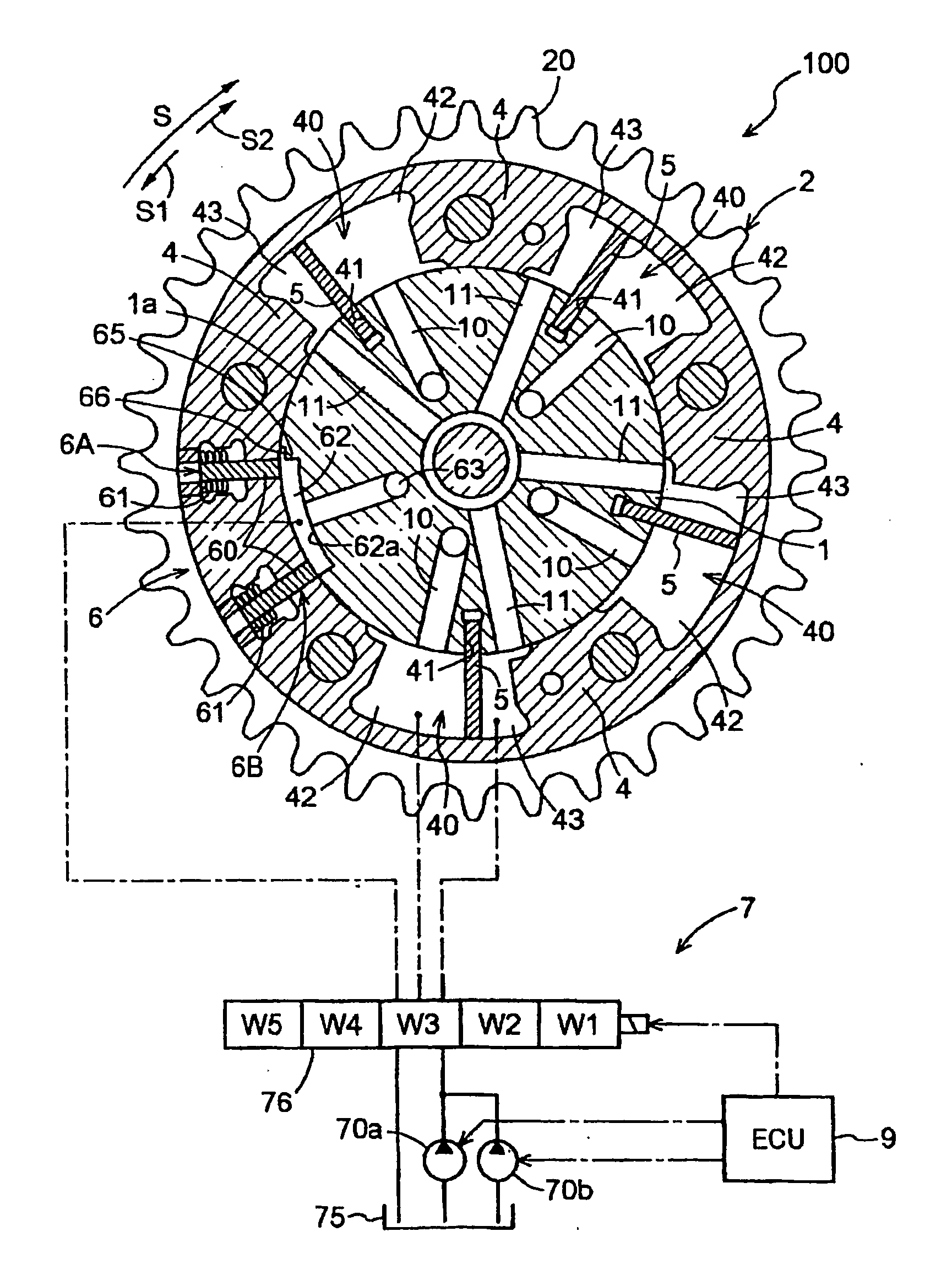
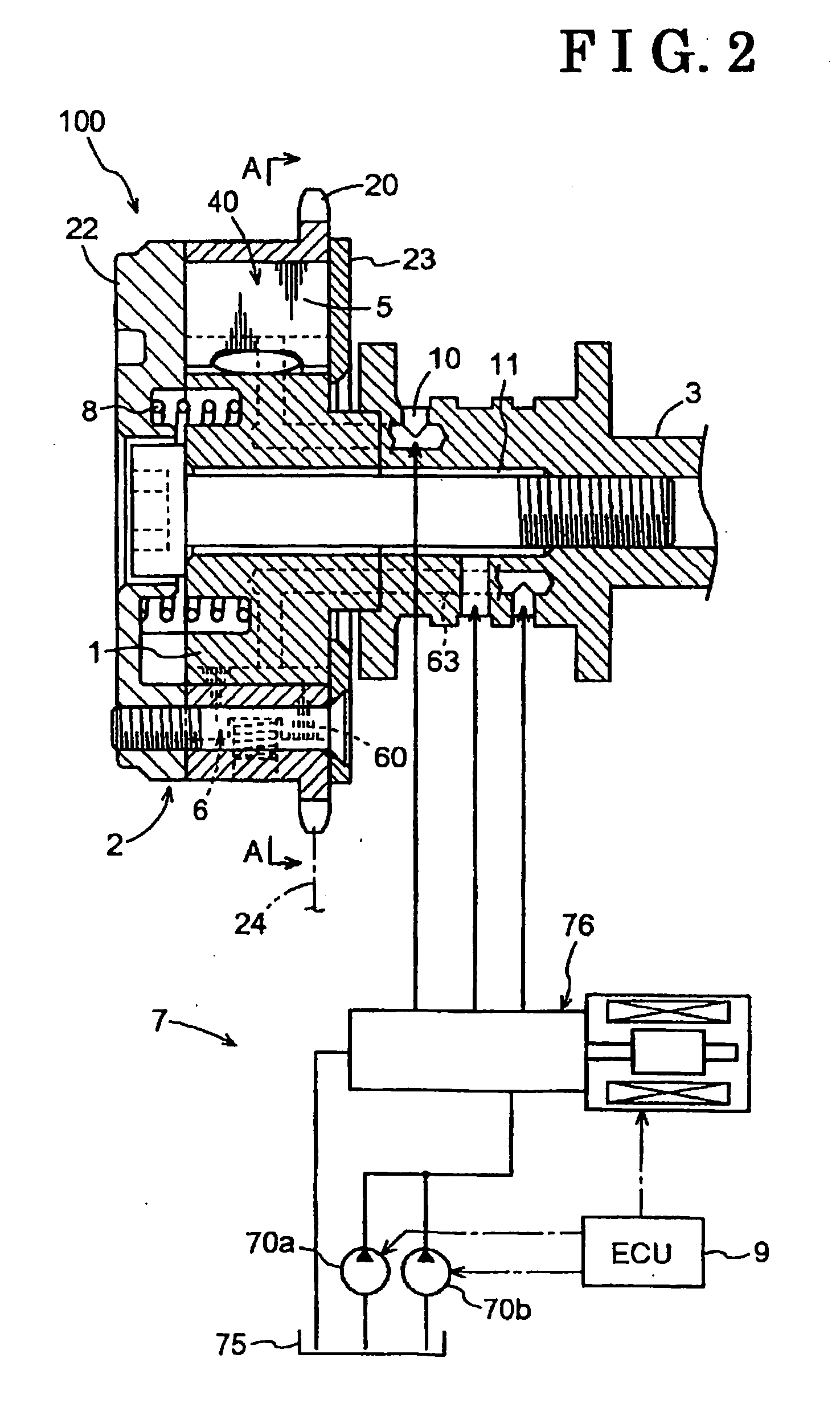
[0136]As is illustrated in FIG. 11, in a variable valve timing control apparatus 1 according to the second embodiment of the present invention, the first pump 70a is arranged in series with the second pump 70b, while other configuration thereof is substantially identical to the first embodiment.

[0137]According to the second embodiment of the present invention, the second pump 70b is arranged in series with and on the downstream side of the first pump 70a. An oil reservoir 71 is provided between the first pump 70a and the second pump 70b. This oil reservoir 71 can store an amount of oil drawn from the oil pan 75 by the first pump 70a. When the first pump 70a is operating, oil is supplied to each portion of the engine E via a main oil passage 72 from the oil reservoir 71, and is supplied to the variable valve timing control unit 100 via the control valve 76. When the first pump 70a is inoperative in response to the halt of the engine E, the second pump 70b draws oil accumulated in the...

third embodiment

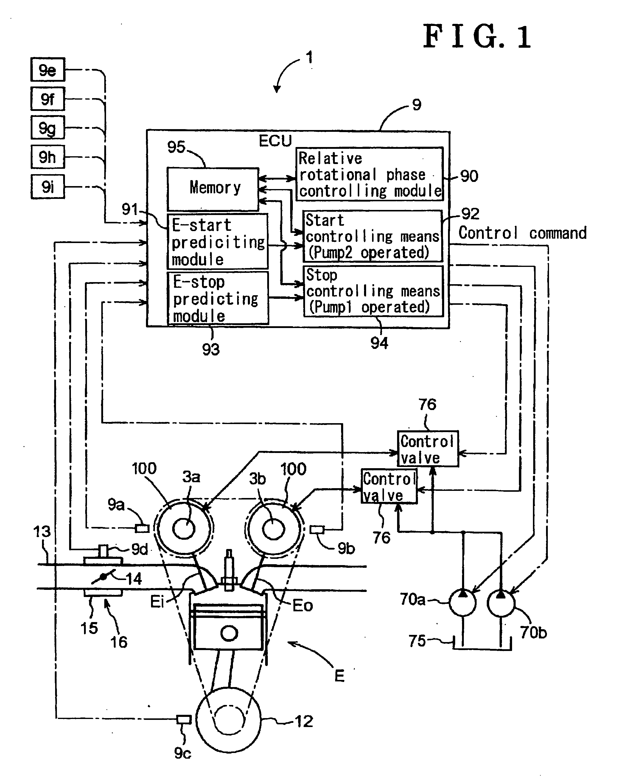
[0139]As is illustrated in FIG. 12, a variable valve timing control apparatus 1 according to a third embodiment of the present invention is provided with an engine stop delaying module (an engine stop delaying means) 96, while other configuration thereof is substantially identical to the first embodiment. Further, FIG. 12 illustrates an engine-controlling module (an engine controlling means) 110 which is not shown in other figures. However, this engine-controlling module 110 is provided in the apparatus 1 according to the other embodiments.

[0140]According to this third embodiment, in accordance with predetermined conditions described later, the engine stop control is performed in such a manner that the predetermined intermediate lock is carried out after delaying the halting of the operation of the first pump 70a. The operations relevant to this engine stop control are illustrated in the flowchart in FIG. 14. In this flowchart, the module (means), which carries out respective step, ...

fourth embodiment

[0158]As is illustrated in FIG. 13, the variable valve timing control apparatus according to the fourth embodiment of the present invention is provided with an engine stop operation predicting module (an engine stop operation predicting means) 97, while other configuration thereof is substantially identical to the first embodiment. FIG. 13 illustrates a driven system 160 which is not illustrated in other figures. However, this driven system 160 is provided in the apparatus 1 according to the other embodiments.

[0159]Here, an engine stop operation predicting control is performed by means of the engine stop operation-predicting module 97. The engine stop operation predicting control is a one implemented based on a predetermined predicted condition such as an engine stop operation (e.g. a turning of the ignition key 9e to its off position). This predetermined condition is described later.

[0160]The engine stop operation-predicting module 97 is incorporated in the ECU 9 illustrated in FIG...


PUM


Abstract

A variable valve timing control apparatus includes: a relative rotational phase adjusting mechanism capable of adjusting a relative rotational phase between a drive-side rotational member and a driven-side rotational member between the most advanced angle phase and the most retarded angle phase; and a lock mechanism capable of locking the relative rotational phase at an intermediate phase between the most advanced angle phase and the most retarded angle phase; a first pump operated by a driving force of an engine; and an electrically driven second pump operated as an electrically driven pump. Hydraulic fluid is supplied from at least one of the first pump and the second pump, and the second pump is capable of operating even if the first pump is inoperative when the engine is not running.

Description

TECHNICAL FILED[0001]This invention generally relates to a variable valve timing control apparatus which controls opening and closing timings of one of, or both of, an intake valve and an exhaust valve, in response to running conditions of an engine mounted for example on a vehicle.BACKGROUND ART[0002]This type of variable valve timing control apparatus is mainly configured with a variable valve timing control unit and a relative rotational phase adjusting mechanism. The variable valve timing control unit incorporates, therein, a drive-side rotational member, which rotates in synchronization with a crankshaft; a driven-side rotational member, which is positioned coaxially with the drive-side rotational member and rotates integrally with a camshaft; at least one fluid pressure chamber defined in at least one of the drive-side rotational member and the driven-side rotational member; at least one vane dividing the fluid pressure chamber into an advanced angle chamber and a retarded ang...

Claims


Application Information

Patent Timeline
Patent Type & Authority Applications(United States)
IPC IPC(8): F01L1/344F01L1/34F02D13/02F02D17/00F02D41/04F02D41/06F02D45/00F02N15/00F02N99/00
CPCF01L1/3442F01L2001/34483F01L2001/34476F01L2001/34426
Inventor MATSUSAKA, MASANOBUYUMISASHI, NAOTOEGUCHI, KATSUHIKOSUZUKI, SHIGEMITSUKANADA, YOJIHASHIZUME, TAKESHI
Owner AISIN SEIKI KK
Why Eureka
Try Eureka