

Solar water vapor ejector
- Summary
- Abstract
- Description
- Claims
- Application Information
AI Technical Summary
Benefits of technology
Problems solved by technology
Method used
Image

Examples
Embodiment Construction
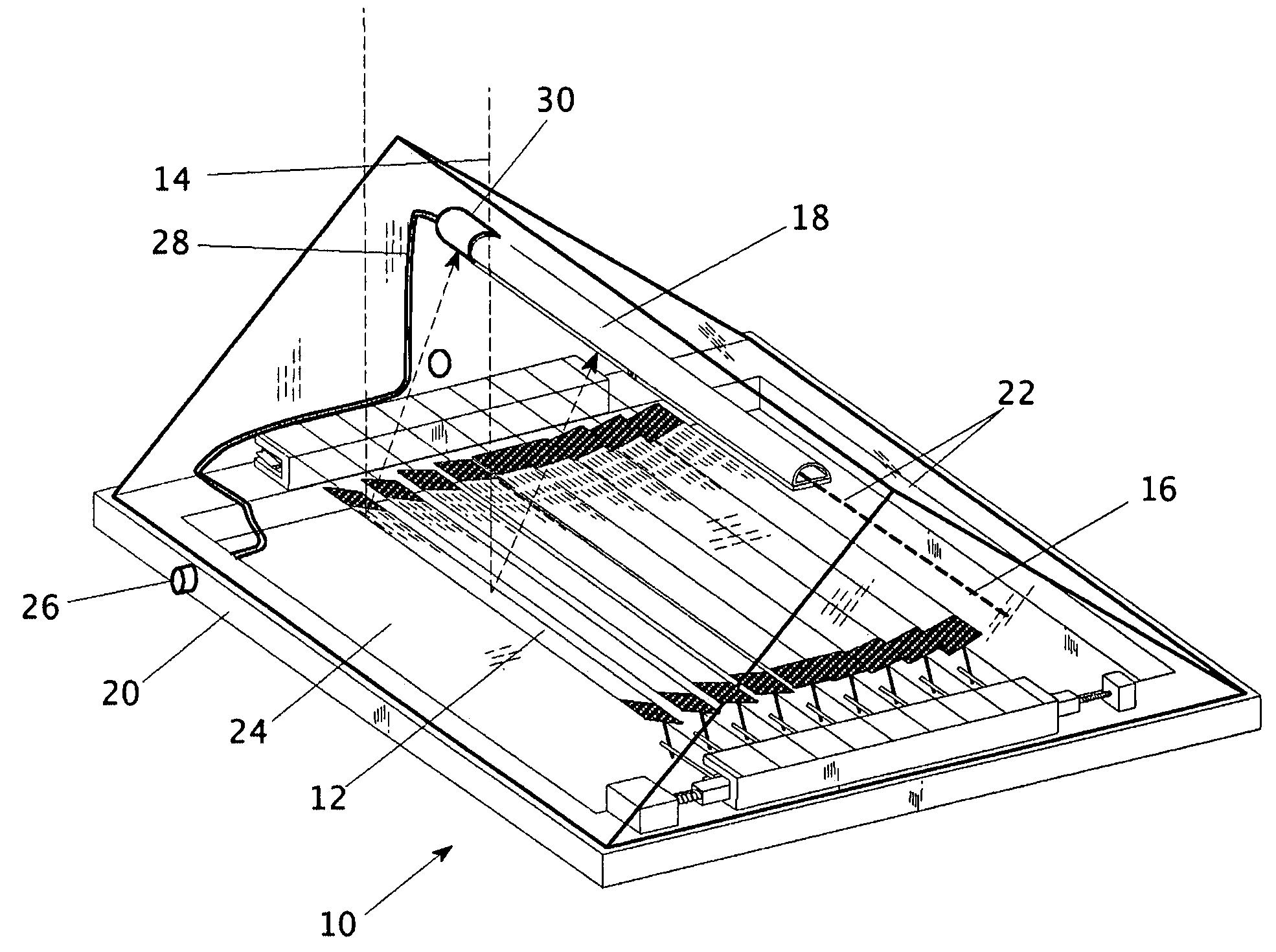
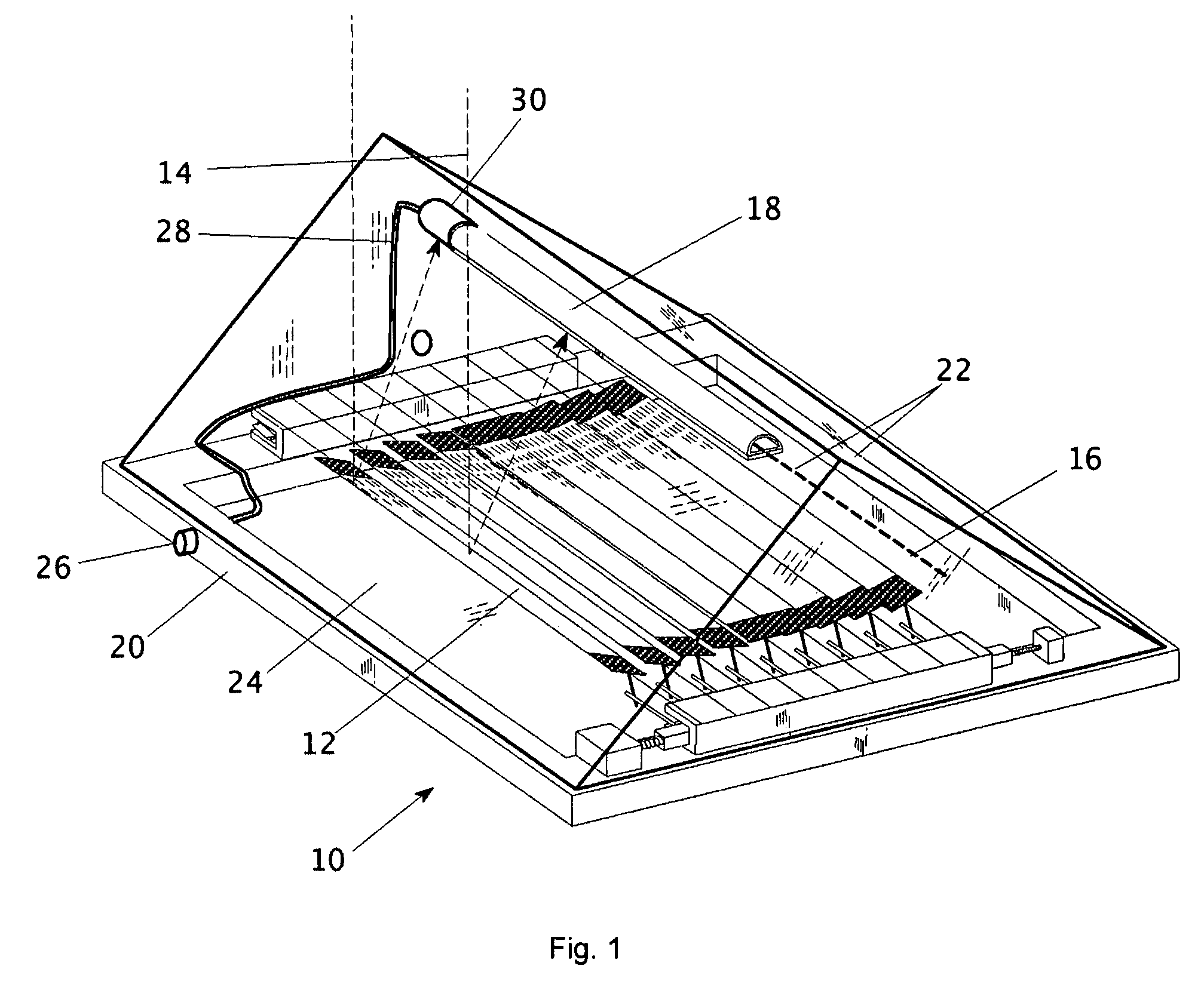
[0038]Referring first to FIG. 1, reference numeral 10 generally designates a dust-tight enclosure for a solar power harvester. A taught in prior art, the solar power harvester may be a planar array of photovoltaic cells or heat-absorbing coolant pipes; it may be a concentrating collector such as a parabolic dish or parabolic trough; or as illustrated here: a Fresnel collector comprised of a planar array of reflective slats 12 positioned to each reflect sunlight 14 onto a common focus 16. The sunlight impinges on a solar converter 18 at the common focus 16 which converts the solar irradiation 14 into useful power by photovoltaic cells (PV) which generate electricity and / or blackened pipes which heat an internal working fluid.
[0039]The dust-tight enclosure 10 comprises a base 20, upper transparent window or windows 22, and a sealed bottom covering 24. The window is typically a glass which is highly transparent to the solar spectrum and typically is anti-reflection coated. The sealed b...
PUM
 Abstract
Description
Claims
Application Information