Disc protector

a technology for optical data storage and discs, applied in the direction of record carrier construction details, containers, packaging goods, etc., can solve the problems of degrading the transparent surface layer which covers, affecting the appearance of obscuring the surface texture to the original high-polished surface, so as to avoid the possibility of disc reading devices and no additional complexity in disc handling.

Inactive Publication Date: 2009-01-29
LAWCOCK ROGER
View PDF7 Cites 0 Cited by
  • Summary
  • Abstract
  • Description
  • Claims
  • Application Information

AI Technical Summary

Benefits of technology

[0009]Hence it is the objective of the current invention to provide a method of disc protection without the disadvantages of prior disclosures. It is further an objective of the invention to provide a method for the protection of discs while they are stored in conventional disc cases such that documentation can be retained with the disc, and the disc content can be determined by viewing the external spine when large quantities of discs are stored in their cases either in vertical stacks or in horizontal rows. The invention does not require the addition of material to the disc, hence the potential for interference with disc reading devices is avoided.
[0010]The objectives are achieved by the provision of a protective insert that separates the disc holder surface from the disc surface. The insert is of the form of a thin annulus and can be placed or affixed into conventional disc holders such that disc protection may be achieved at low cost, with no additional complexity in disc handling and provides the use of conventional disc holders.

Problems solved by technology

A problem with such discs relates to degradation of the transparent surface layer which covers the inner data-containing material.
In normal use and handling, the transparent layer can become damaged, even small surface flaws, over time, may accumulate and produce an obscured surface texture to the originally highly polished surface.
Eventually the surface degradation may reach such a level that the data-reading device can no longer read data that is present on the inner data-containing surface.
Such loss of data reading ability can be catastrophic since the preciously recorded data on the disc can no longer be recovered.
In the cited, but not inexhaustible examples of use given above, i.e. business, industrial, scientific, home and entertainment applications, loss of use of the disc and its data content is obviously inconvenient.
For example, recorded business-data and digital photographs may become un-retrievable, data, music and video files may not be able to be recovered hence rendering the discs unplayable in audio, video and computer game applications.
When out of their storage case, and in use, it is obvious that discs can accumulate damage to the protective layer depending upon how the discs are manually handled or stored before being returned to the storage case.
A common drawback of such standard disc-cases is that the data-access surface of the disc may contact against the inner faces of the case such that the surface of the disc becomes scratched.
Therefore when a jewel case is moved, the CD contained inside can become damaged due to relative motion and contact between the disc and the case.
Repeated scratching of the surface of the disc can lead to the situation where the data that is present can longer be accessed by the reading device.
A method of disc protection using a layered disc approach is shown in U.S. Pat. No. 4,736,840 where the data-disc is located between other protecting discs, the layered assembly is costly and imposes additional practical complexity in disc handling.
A protection method is shown in U.S. Pat. No. 4,850,731 by disc storage in flexible and soft envelopes, however the method precludes use of conventional disc holders and therefore disc titles or content cannot be viewed when large numbers of discs are stored in vertical stacks or in horizontal rows.
A method of supporting the data-access surface by soft rings of material is shown in U.S. Pat. No. 5,299,186, however the method relates to storage of discs outside of the standard case, hence there is a disadvantage in that the supporting documentation is not carried with the disc, also in storage of a large quantity of discs, the title or content of the disc cannot be viewed.
Application of transparent outer shells or layers to the disc has been described for example in U.S. Pat. No. 5,787,069 and U.S. Pat. No. 6,240,061, which increase the thickness of the disc and hence may interfere with the data reading device.
A method of raising the outer diameter portion of the disc by application of a flexible band is described in U.S. Pat. No. 5,848,687 the flexible band may not fully protect the data access portion of the disc, and the flexible band may undesirably interfere with the disc reading device.
Modification of the disc holder to incorporate a central-hub and raised-ribs is disclosed in U.S. Pat. No. 6,409,014 however the raised rib supports are manufactured form relatively hard material that may damage the disc, also the special shape prevents the use of conventional disc holders.
A method of adhesively attaching rings of supportive material to the inner and outer regions of the disc is described in U.S. Pat. No. 6,667,953 however the undesirable increased disc thickness may pose problems with disc reading devices.
WO 2005 / 070698 A1 describes methods of disc storage comprising flexible sheets, however the proposed construction is not usable with conventional disc holders, hence in storage of a quantity of discs the title or content of the disc inconveniently cannot be viewed.

Method used


Image

  • Disc protector
  • Disc protector
  • Disc protector

Examples


Embodiment Construction

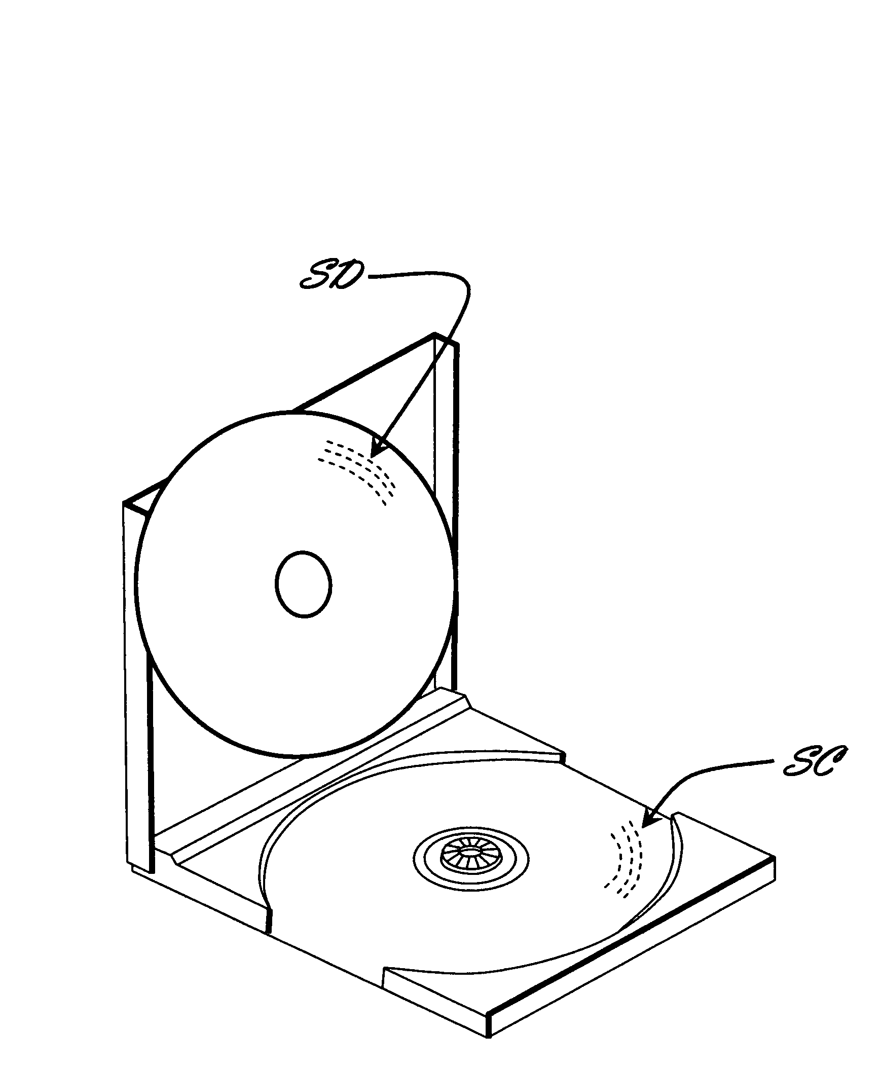
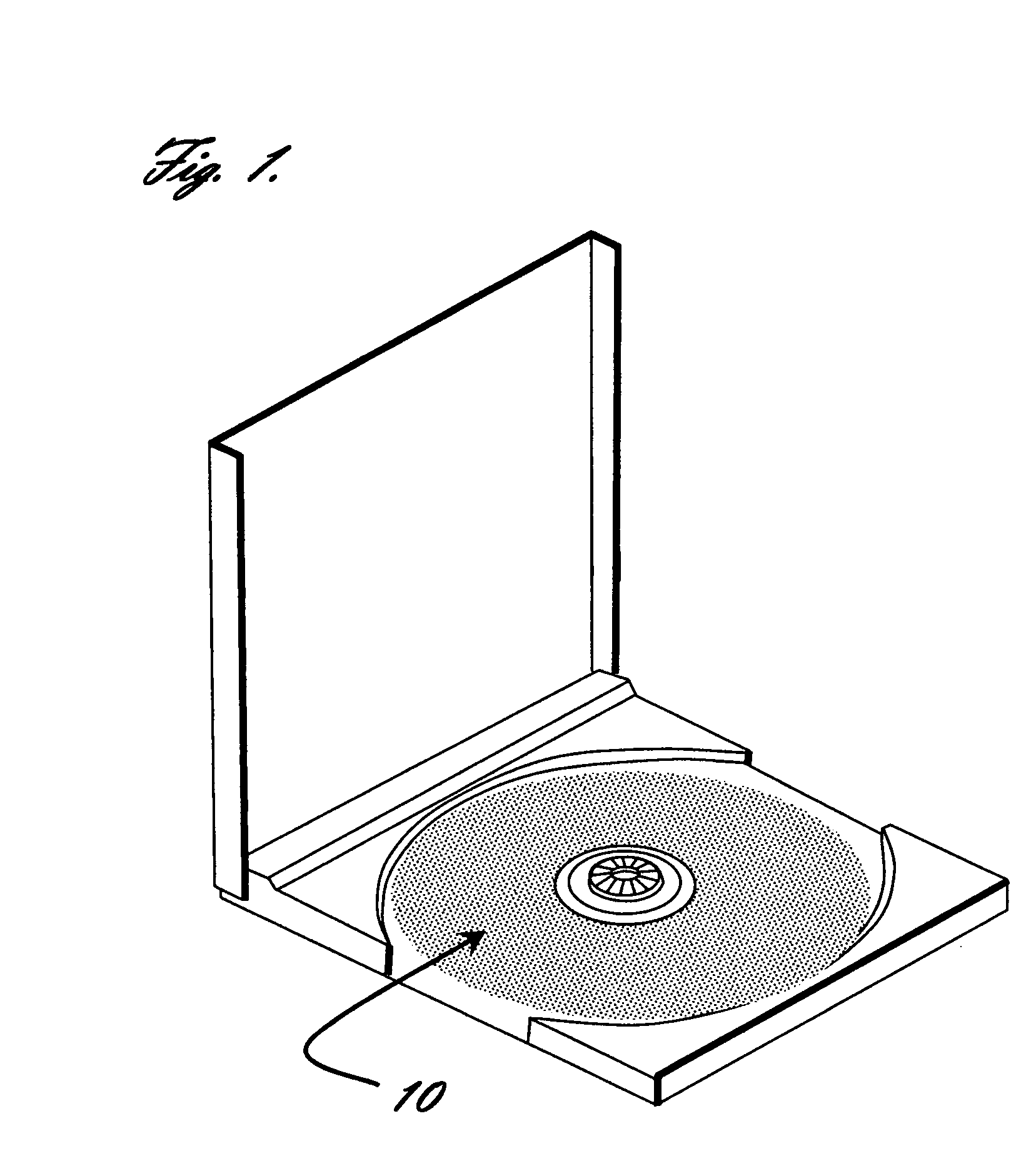
[0018]FIG. 1 shows the essence of the new invention where a protective layer 10 is introduced into the base of the disc holder.

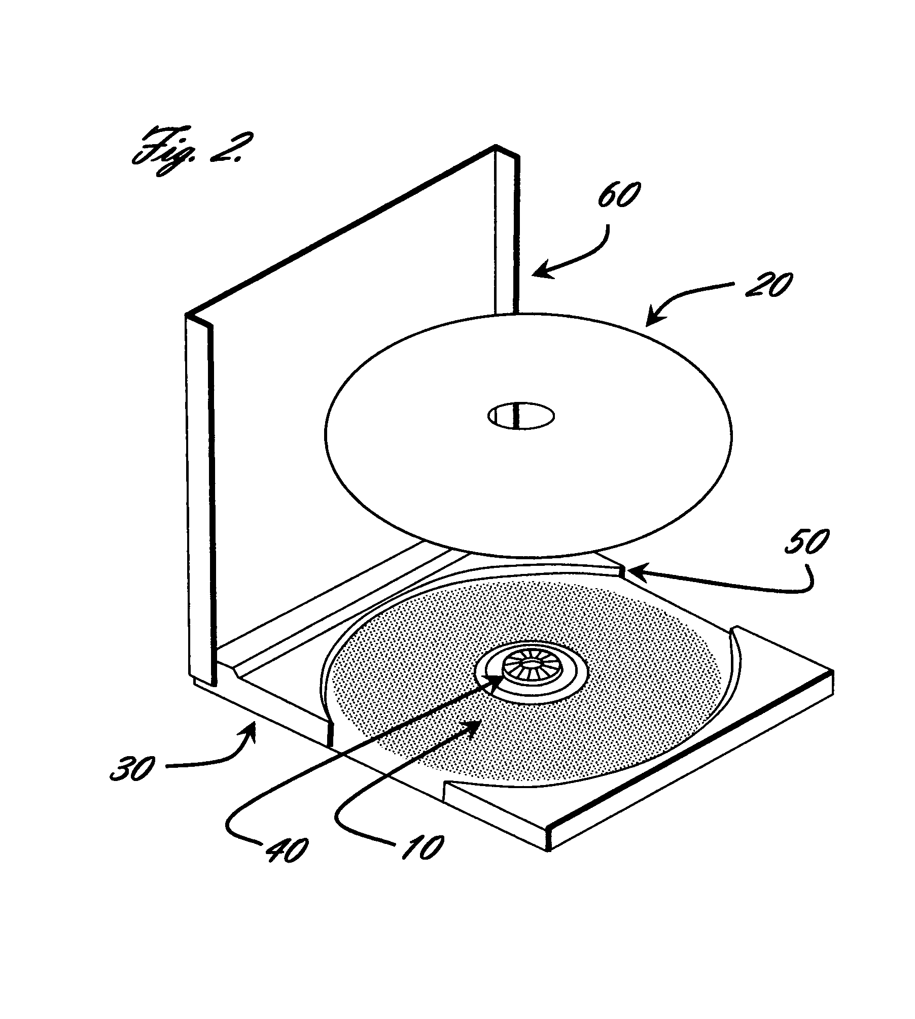
[0019]FIG. 2 shows the general arrangement for disc storage cases where the disc 20 installs into the base 30, consisting of an integrally formed central hub 40, and a formed recess 50, the case then be closed with the hinged lid 60.

[0020]FIG. 3 shows a disc installed in the disc holder, with the hinged lid in the open position, to reveal section A-A which is used to provide further detailed description of the invention.

[0021]FIG. 4 shows the section at A-A for a disc that is located in conventional disc holder. The disc 20 is shown mounted on the central hub 40 in view B, further the disc 20 is shown to comprise of three layers, a backing layer 70, a central data containing layer 80 and an optically transparent protective layer 90. Typical dimensions of the discs 20 are 120 mm in diameter, a central spindle hole diameter of 15 mm and a thickness of 1.2 mm. ...


PUM

PropertyMeasurementUnit
inner diameteraaaaaaaaaa
outer diameteraaaaaaaaaa
thicknessaaaaaaaaaa

Abstract

A disc protector is described for use in the field of optical data storage discs where commonly known applications are compact discs (CD), digital versatile discs (DVD) and super audio compact discs (SACD). In particular a method to improve disc-holders is described where a protective material is present between the data-access surface of the disc and the disc-holder.

Description

REFERENCES CITED[0001]U.S. Pat. No. 4,736,840. Apr. 12, 1988, Deiglmeier.U.S. Pat. No. 4,850,731. Jul. 25, 1989, Youngs.U.S. Pat. No. 4,879,710. Nov. 7, 1989, Iijima.U.S. Pat. No. 4,983,437. Jan. 8, 1991, Merrick.U.S. Pat. No. 5,299,186. Mar. 29, 1994, TsurushimaU.S. Pat. No. 5,787,069. Jul. 28, 1998, Lowe et al.U.S. Pat. No. 6,240,061. May 29, 2001, Burroughs.U.S. Pat. No. 5,848,687. Dec. 15, 1998, Shultz.U.S. Pat. No. 6,409,014. Jun. 25, 2002, Hummel et al.U.S. Pat. No. 6,667,953. Dec. 23, 2003, Matson et al.WO 2005 / 070698 A1. Aug. 4, 2005, Ludvigsen.EP 1,489,618 A2. Dec. 22, 2004. Kondo.[0002]http: / / envelopes.tyvek.com / en / applications / styles_disc.shtmlhttp: / / www.dupont.com / nonwovens / ap / sontara.htmlFIELD OF THE INVENTION[0003]The invention has application to the protection of optical data storage discs when they are located in conventional disc holders.BACKGROUND OF THE INVENTION[0004]The invention relates to the protection of optical data storage discs that are used in a variety ...

Claims


Application Information

Patent Timeline
Patent Type & Authority Applications(United States)
IPC IPC(8): G11B33/04
CPCG11B33/0427
Inventor LAWCOCK, ROGER
Owner LAWCOCK ROGER
Why Eureka
Try Eureka