Spiral membrane element and process for producing the same

a technology of spiral membrane element and spiral membrane, which is applied in the direction of membrane, filtration separation, separation process, etc., can solve the problems of long time, cumbersome and time-consuming steps, and disadvantage in terms of materials cost,

Inactive Publication Date: 2009-01-29
NITTO DENKO CORP
View PDF19 Cites 41 Cited by
  • Summary
  • Abstract
  • Description
  • Claims
  • Application Information

AI Technical Summary

Benefits of technology

The present invention provides a simple process for making a spiral membrane element that can form a uniform fiber reinforcement layer on its outer surface without changing the materials used. This results in a more efficient and cost-effective production process.

Problems solved by technology

The technical problem addressed in this patent is to simplify the production process and reduce costs associated with the production of a spiral membrane element used for reverse osmosis filtration and micro filtration.

Method used


Image

  • Spiral membrane element and process for producing the same
  • Spiral membrane element and process for producing the same
  • Spiral membrane element and process for producing the same

Examples


example 1

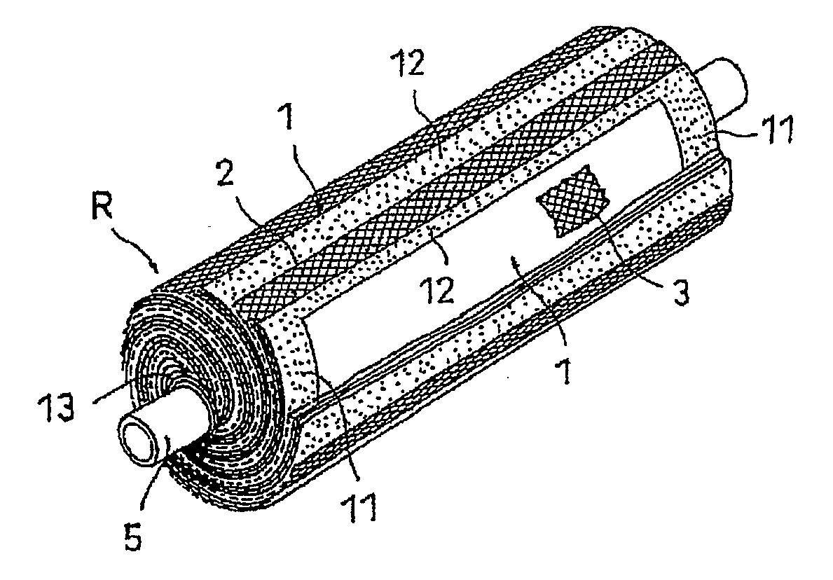
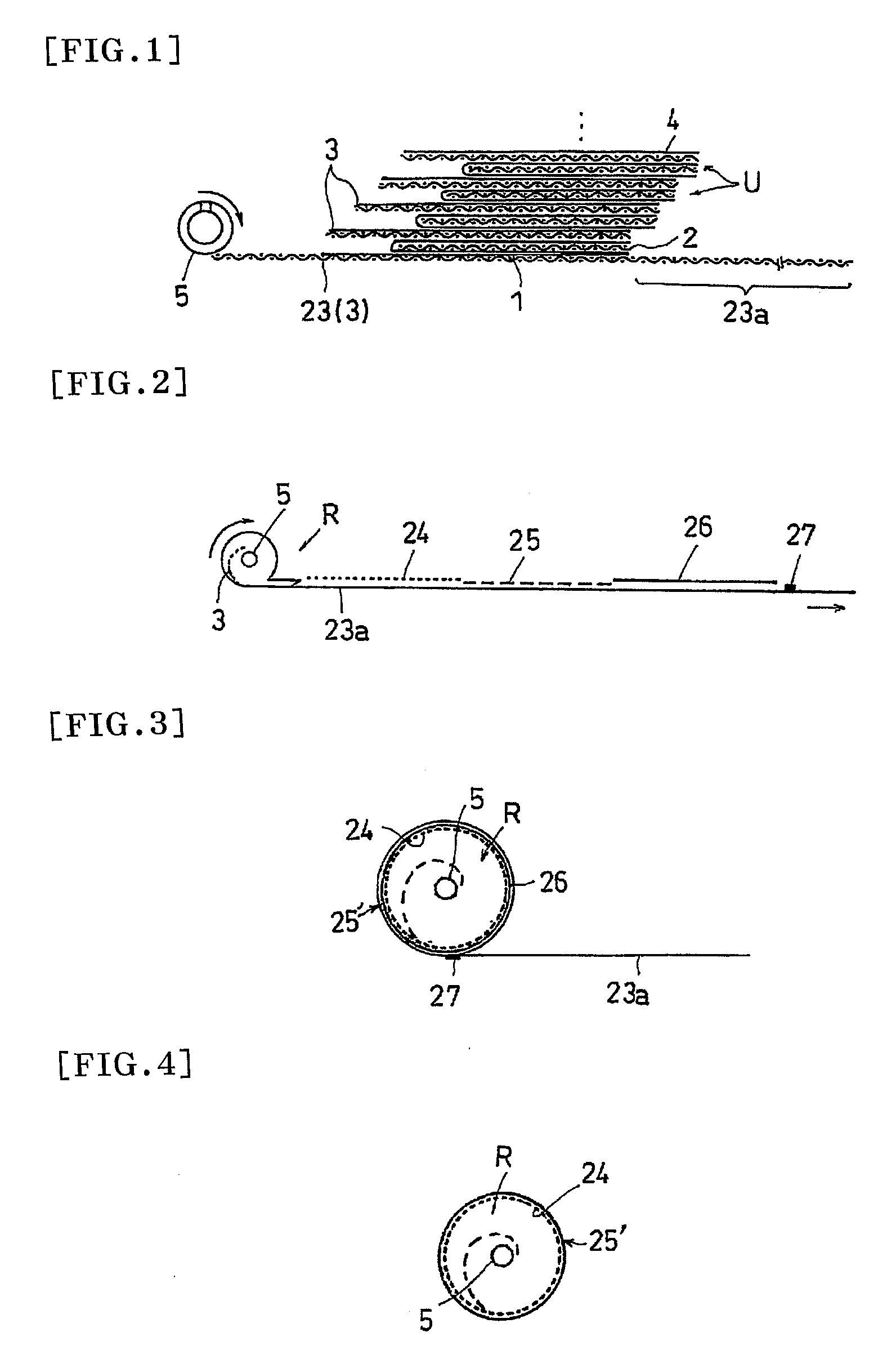
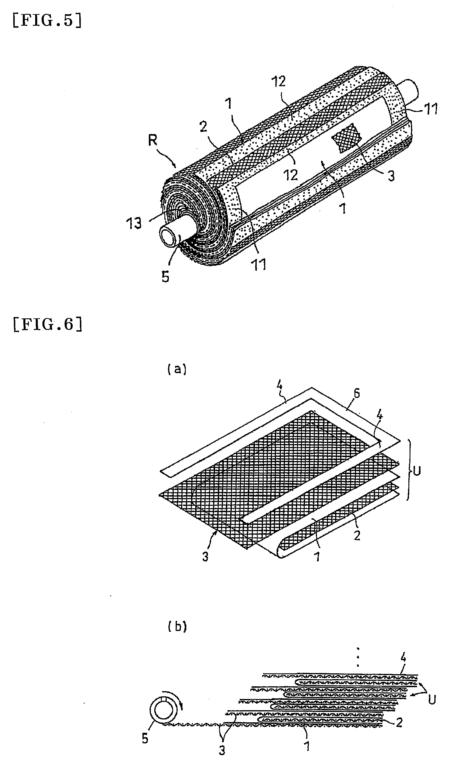
[0079]First, a membrane leaf unit made of an RO membrane ES20 manufactured by Nitto Denko Corporation. and a feed-side flow passageway member made of PP and having a thickness of 0.7 mm was prepared. Next, the tip end of the permeate-side flow passageway member made of PET and having a thickness of 0.3 mm was fixed to a hollow center tube made of PPE and having a diameter of 32 mm, and the membrane leaf unit was mounted on the permeate-side flow passageway member while applying a polyurethane resin at the part corresponding to the sealing part.

[0080]Next, the mounted membrane leaf unit was wound while rotating the hollow center tube around the axis and applying a tension. Subsequently after the membrane leaf unit was wound, a resin sheet for display was wound by the length corresponding to the circumferential length of the roll. Next, the permeate-side flow passageway member at the back of the resin sheet was impregnated with a polyurethane resin over the entire surface by the lengt...

example 2

[0083]A spiral membrane element was fabricated in the same manner as in the Example 1 except that an adhesive having a thixotropy property (a polyurethane resin, a two-liquid type adhesive that mixes polyurethane and polyisocyanate) was used as the adhesive of the sealing part, and an epoxy resin having a low viscosity (a two-liquid setting resin that mixes a bisphenol A type epoxy resin and a polyamideamine) was used as the resin to be applied to the permeate-side flow passageway member in the Example 1. Here, regarding the viscosity of the adhesive and the viscosity of the above-described resin, those having 28000 mPa·s and 2000 mPa·s, respectively, as measured by using a #6 rotor in a BH-type viscometer under the condition of 20 rpm, were used.

[0084]At the time of applying the adhesive and in the stationary state after winding, the adhesive had not been fluidized and the shape had been retained. At the time of winding, a sealing part without the drop-off of the resin could be for...


PUM

PropertyMeasurementUnit
Viscosityaaaaaaaaaa
Viscosityaaaaaaaaaa
Angular velocityaaaaaaaaaa

Abstract

An object of the present invention is to provide a spiral membrane element that can form a uniform fiber reinforcement layer on an outer circumferential surface by a simple process without a great change in the materials, as well as a process for producing the same. The spiral membrane element of the present invention is a spiral membrane element which is provided with a cylindrical roll R in which a separation membrane, a feed-side flow passageway member, and a permeate-side flow passageway member 3 are spirally wound in a laminate state around a perforated center tube 5 and in which a sealing part for preventing mixing of feed-side fluid and permeate-side fluid is disposed, wherein at least one sheet of the permeate-side flow passageway member 3 has a fiber cloth 23a extended or connected to the outer circumferential side, and the fiber cloth 23a is wound around an outer circumference of said cylindrical roll R, impregnated with a resin and hardened to thereby form a fiber reinforcement layer.

Description


Claims


Application Information

Patent Timeline
Owner NITTO DENKO CORP
Why Eureka
Try Eureka