Attachment for a magnetic structure

a magnetic structure and magnetic core technology, applied in the direction of dynamo-electric machines, electrical apparatus, magnetic circuit shapes/forms/construction, etc., can solve the problems of significant affecting the overall performance of the machine, affecting the power efficiency, etc., and achieves low mechanical stress, low cost, and the effect of maximizing the contact area

Inactive Publication Date: 2009-01-29
VESTAS WIND SYST AS
View PDF13 Cites 26 Cited by
  • Summary
  • Abstract
  • Description
  • Claims
  • Application Information

AI Technical Summary

Benefits of technology

[0018]It is yet still another object of the present invention to provide an attachment of the type described above which is configured to exhibit a relatively low level of mechanical stress.
[0019]It is another object of the present invention to provide an attachment of the type described above which is configured to maximize the area of contact with the radial tooth on which it is mounted.
[0020]It is yet another object of the present invention to provide an attachment of the type described above which is durable, has a limited number of parts, is inexpensive to manufacture and is easy to install.

Problems solved by technology

Although well-known in the art, a magnetic core which utilizes an open slot design suffers from a notable drawback.
Specifically, it has been found that an open slot design can significantly compromise the overall performance of the machine (e.g., power efficiency).
In particular, it has been found that electric machines which include a magnetic core with an open slot design often suffer from, among other things, significant increases in slot harmonics, magnetic flux leakage and cogging torque (i.e., vibration), which are all highly undesirable.
Specifically, because integral tooth tips significantly reduce the slot gap between adjacent teeth, it has been found to be rather difficult, if not impossible, to insert magnetic coils into each slot along a radial path.
Rather, winding coils can only be inserted into each slot along an axial path, thereby complicating the coil packing process, which is highly undesirable.
Otherwise, the tooth tip is susceptible to either fragmentation or complete separation from the magnetic core tooth during operation of the machine.
As can be appreciated, the requirement that each tip be constructed using strong materials limits machine manufacturers from considering weaker materials that are considerably less expensive, which is highly undesirable.
Consequently, if the winding coils (and wedge) are packed too tightly within a slot, axial installation of the tip on the magnetic core tooth can not be readily achieved.
As can be appreciated, this rearrangement of the steps of assembly substantially reduces the maximum number (i.e., density or slot fill percentage) of coils that can be packed within each slot which, in turn, limits the performance characteristics of the machine, which is highly undesirable.

Method used


Image

  • Attachment for a magnetic structure
  • Attachment for a magnetic structure
  • Attachment for a magnetic structure

Examples


Embodiment Construction

Construction of Stator 11

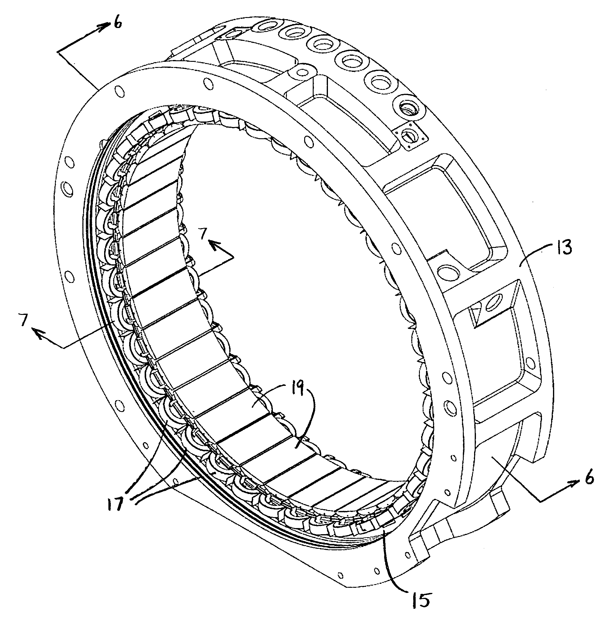
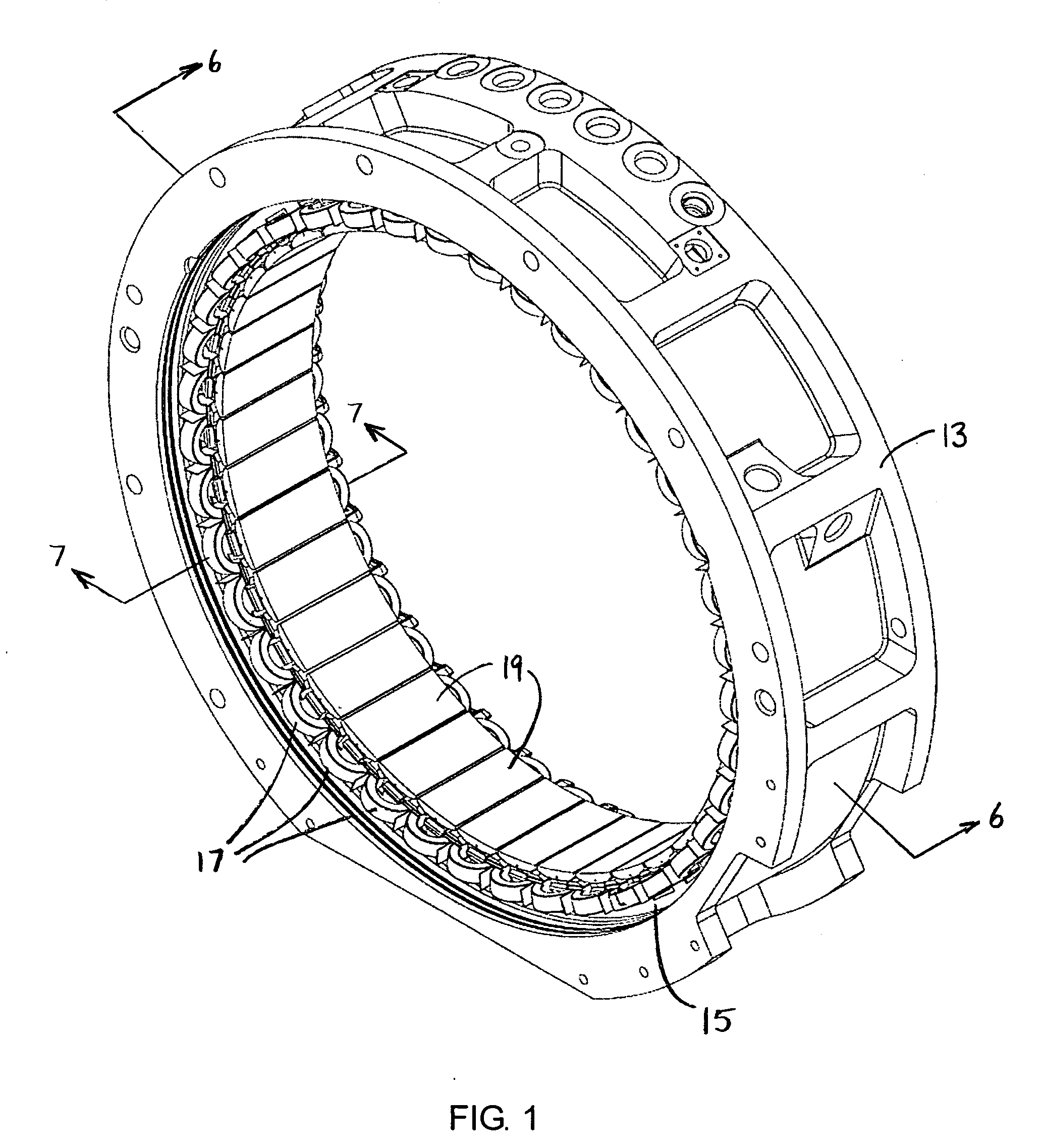
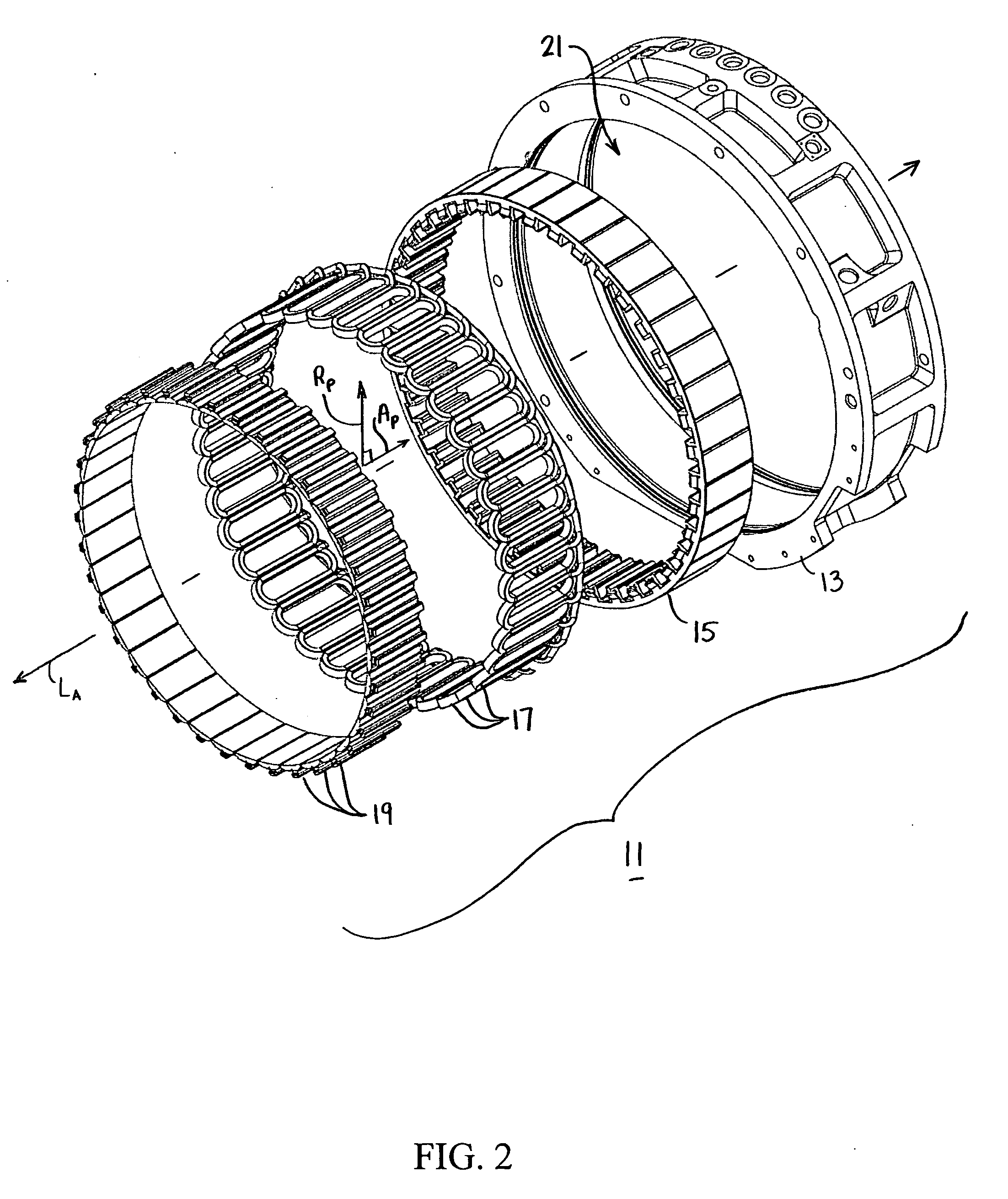
[0034]Referring now to FIGS. 1 and 2, there are shown perspective and exploded perspective views, respectively, of a stator for a rotating electric machine, the stator being constructed according to the teachings of the present invention and identified generally herein by reference numeral 11.

[0035]Stator 11 comprises an outer frame 13, a magnetic core 15 held within frame 13, a plurality of magnetic coils 17 packed within slots formed in magnetic core 15, and a plurality of conductive attachments, or tips, 19 which matingly engage with magnetic core 15 to both (i) optimize the magnetic lines of flux that conduct through core 15 and (ii) assist in retaining coils 17 in place. As will be described in detail below, the particular design of the mating interface between magnetic core 15 and tips 19 serves as the principal novel feature of the present invention.

[0036]As seen most clearly in FIG. 2, outer frame, or back iron, 13 is a rigid and durable member which...


PUM


Abstract

Attachments are removably coupled to the magnetic core of a rotating electric machine, the magnetic core being shaped to include a plurality of coil-receiving slots that are separated by radial teeth. Each attachment is constructed as a unitary member and includes a base and a stem, the stem being dimensioned for fitted insertion within a recess formed in the distal end of a corresponding tooth. The base includes a convex bottom wall, a flattened top wall and a pair of non-planar sidewalls. The stem is integrally formed on the top wall of the base and includes a front end, a rear end, a flattened top wall and a pair of opposing sidewalls. A longitudinal groove is formed into each of the pair of opposing sidewalls of the stem. An outwardly protruding shoulder designed for engagement by a retention plate is formed into the front and rear ends of the stem.

Description

CROSS-REFERENCE TO RELATED APPLICATIONS[0001]The present application claims the benefit under 35 U.S.C. 119(e) of U.S. provisional Patent Application Ser. No. 60 / 922,266, filed Apr. 6, 2007, the disclosure of which is incorporated herein by reference.BACKGROUND OF THE INVENTION[0002]The present invention relates generally to rotating electric machines, such as high speed generators and motors, and more particularly to magnetic structures used in rotating electric machines which are shaped to include a plurality of coil-retaining slots that are separated by radial teeth.[0003]In rotating electric machines, such as high speed generators and motors, groups of interconnected conductive coils are commonly wound onto a magnetizable core. To assist in the coil winding process, the magnetic core is often shaped to include a plurality of slots that are separated by radial teeth, or fingers. During assembly, a plurality of the conductive coils is packed within each slot in the magnetic core.[...

Claims


Application Information

Patent Timeline
Patent Type & Authority Applications(United States)
IPC IPC(8): H02K1/18
CPCH02K1/148H02K3/522H02K1/185
Inventor MONGEAU, PETER P.PIERCEY, MARK S.WINK, WILLIAM R.
Owner VESTAS WIND SYST AS
Why Eureka
Try Eureka