Organic light emitting device

a light-emitting device and organic technology, applied in static indicating devices, instruments, semiconductor lamps, etc., can solve the problem of reducing the display quality of active matrix-type organic light-emitting devices, and achieve the effect of improving display quality and stable image display

Inactive Publication Date: 2009-01-29
LG ELECTRONICS INC
View PDF2 Cites 34 Cited by
  • Summary
  • Abstract
  • Description
  • Claims
  • Application Information

AI Technical Summary

Benefits of technology

[0011]An exemplary embodiment provides an organic light emitting device capable of improving the display quality and achieving a stable image display.

Problems solved by technology

However, driving characteristics of the active matrix type organic light emitting device change due to the degradation of subpixel elements such as the transistor, the capacitor, and the organic light emitting diode, and thus the display quality of the active matrix type organic light emitting device is reduced.

Method used


Image

  • Organic light emitting device
  • Organic light emitting device
  • Organic light emitting device

Examples


Embodiment Construction

[0028]Reference will now be made in detail embodiments of the invention examples of which are illustrated in the accompanying drawings.

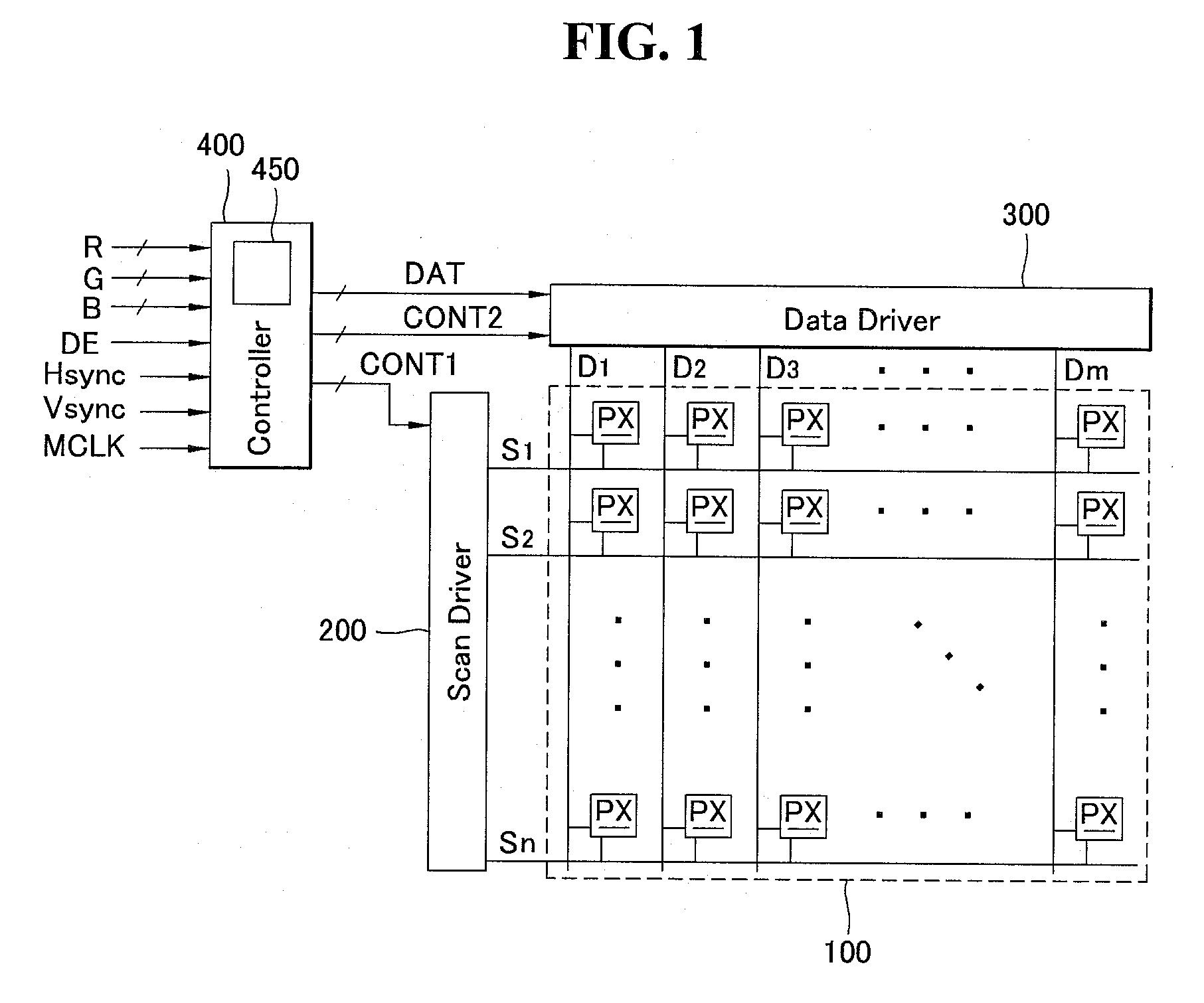
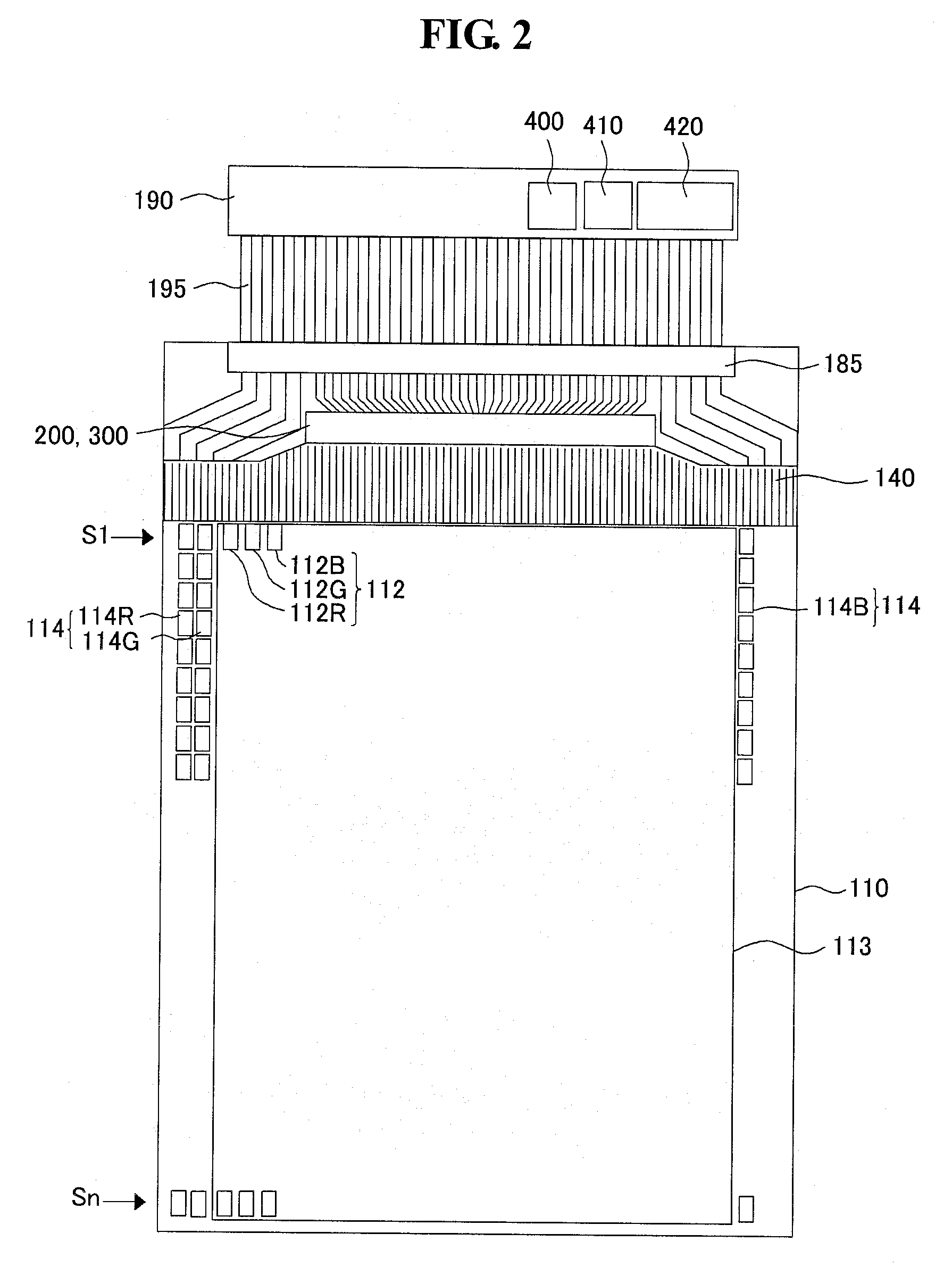
[0029]FIG. 1 is a bock diagram of an organic light emitting device according to an exemplary embodiment, FIG. 2 is a schematic plane view of the organic light emitting device, and FIGS. 3A and 3B are circuit diagrams of a subpixel of the organic light emitting device.

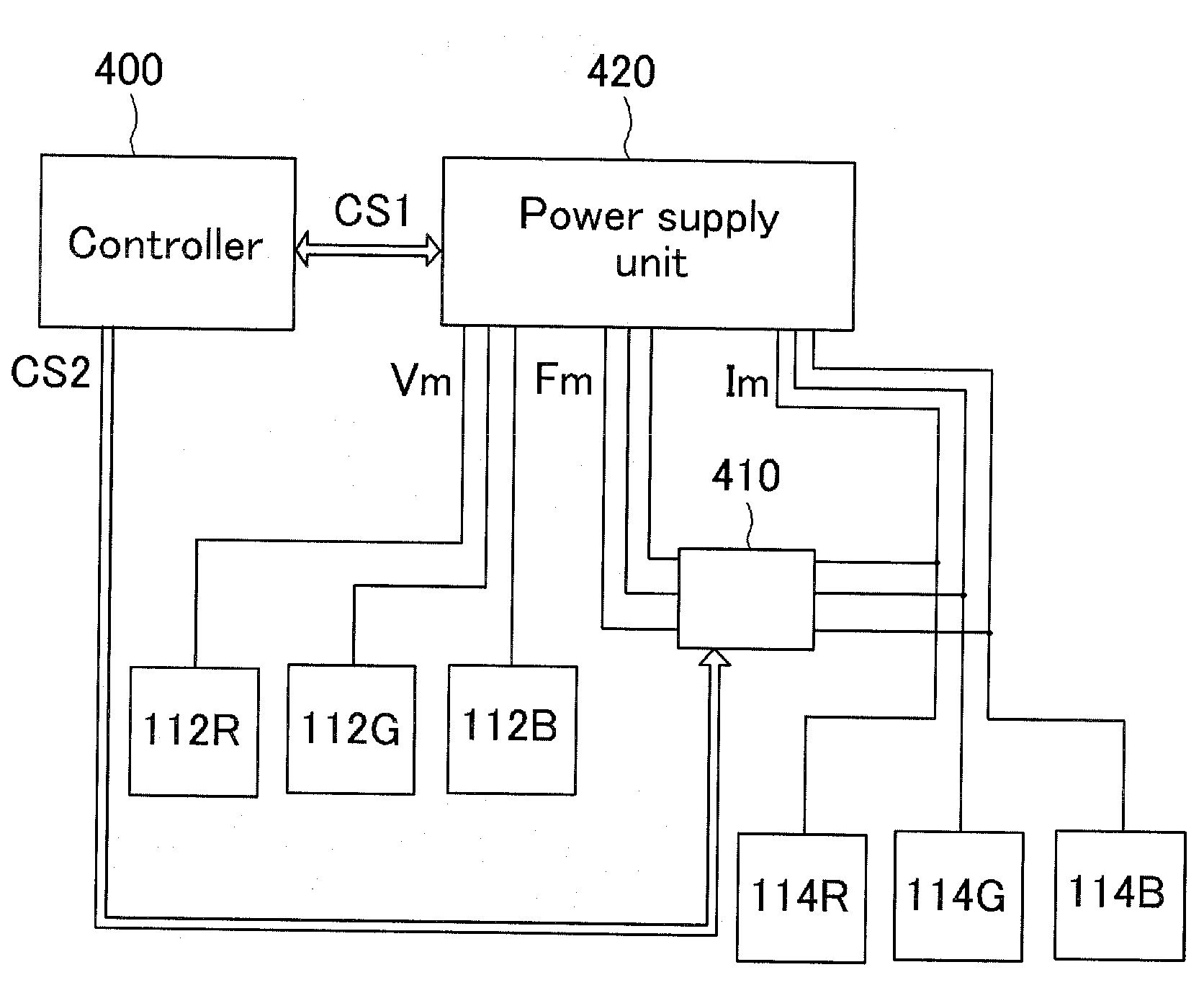
[0030]As shown in FIG. 1, the organic light emitting device according to the exemplary embodiment includes a display panel 100, a scan driver 200, a data driver 300, and a controller 400.

[0031]The display panel 100 includes a plurality of signal lines S1 to Sn and D1 to Dm, a plurality of power supply lines (not shown), and a plurality of subpixels PX arranged in a matrix format to be connected to the signal lines S1 to Sn and D1 to Dm and the power supply lines.

[0032]The plurality of signal lines S1 to Sn and D1 to Dm may include the plurality of scan lines S1 to Sn for transmitting sca...


PUM


Abstract

An organic light emitting device is disclosed. The organic light emitting device includes a display unit on a substrate, the display unit including a plurality of subpixels, a plurality of monitor pixels positioned outside the display unit, a driver that supplies a data signal to the display unit in each of a plurality of subfields, a power supply unit that supplies a power to the display unit and the monitor pixels, and a sample hold unit connected to power terminals of the monitor pixels. When most significant bit is defined as n-bit, the sample hold unit samples a current supplied to the power terminals of the monitor pixels into a voltage in any one of the subfields corresponding to bit equal to or more than (n−2)-bit among the plurality of subfields, and transmits the sampled voltage to the power supply unit.

Description

[0001]This application claims the benefit of Korean Patent Application No. 10-2007-0073990 filed on Jul. 24, 2007, which is hereby incorporated by reference.BACKGROUND[0002]1. Field[0003]An exemplary embodiment relates to a display device, and more particularly, to an organic light emitting device.[0004]2. Description of the Related Art[0005]An organic light emitting device is a self-emitting device including a light emitting layer between two electrodes.[0006]The organic light emitting device may have a top emission structure and a bottom emission structure depending on an emission direction of light. The organic light emitting device may be classified into a passive matrix type organic light emitting device and an active matrix type organic light emitting device depending on a driving manner,[0007]In the active matrix type organic light emitting device, when signals are supplied to a plurality of subpixels arranged on a display unit in a matrix format, a transistor, a capacitor, a...

Claims


Application Information

Patent Timeline
Patent Type & Authority Applications(United States)
IPC IPC(8): H05B41/16G06F3/038
CPCG09G3/2022G09G3/2037G09G3/3208H05B33/0896G09G2310/061G09G2320/029G09G2320/043G09G2310/0262H05B45/60Y02B20/30G09G3/20G09G3/30G09G3/32H05B33/12
Inventor JOO, WOONG
Owner LG ELECTRONICS INC
Why Eureka
Try Eureka