Electric vehicle, and device and method of controlling slip thereof

a technology of electric vehicles and slip control, applied in the direction of electric devices, dynamo-electric converter control, multiple dynamo-motor starters, etc., can solve the problems of difficult control of the rotation speed of the wheel, inability to apply to controlling the slip of left and right wheels, and the wheel of one side slips or tends to be locked. , to achieve the effect of good road holding and stably traveling

Active Publication Date: 2009-01-29
NIPPON YUSOKI
View PDF10 Cites 10 Cited by
  • Summary
  • Abstract
  • Description
  • Claims
  • Application Information

AI Technical Summary

Benefits of technology

[0036]According to the invention, the vehicle can travel stably even on a slippery road surface while keeping good road holding.

Problems solved by technology

There is a problem in those electric vehicles that, since the right and left wheel are driven independently, when the load on the wheel of one side decreases or the friction coefficient of the wheel of one side decreases, only the wheel of one side slips or tends to be locked.
However, with the method of controlling occurrence of slip according to the patent literature 1, when a slip is detected, the first order frequency is gradually increased by allowing it to pass a first delay filter, so the initial slip can be restricted, but when the slip begins it is difficult to control rotation speed of the wheel once the slip occurs.
Therefore, it can not be applied to controlling slips of left and right wheels in consideration of difference between rotation speeds of left and right wheels which occur when the vehicle is turned.
However it is difficult to control rotation speed of the wheel once the slip occurs.
As mentioned above, there are problems in an electric vehicle with motors attached to wheels individually that only the wheel of one side slips or tends to be locked.

Method used


Image

  • Electric vehicle, and device and method of controlling slip thereof
  • Electric vehicle, and device and method of controlling slip thereof
  • Electric vehicle, and device and method of controlling slip thereof

Examples


Embodiment Construction

[0045]Preferred embodiments of the present invention will now be detailed referring accordingly to the accompanying drawings.

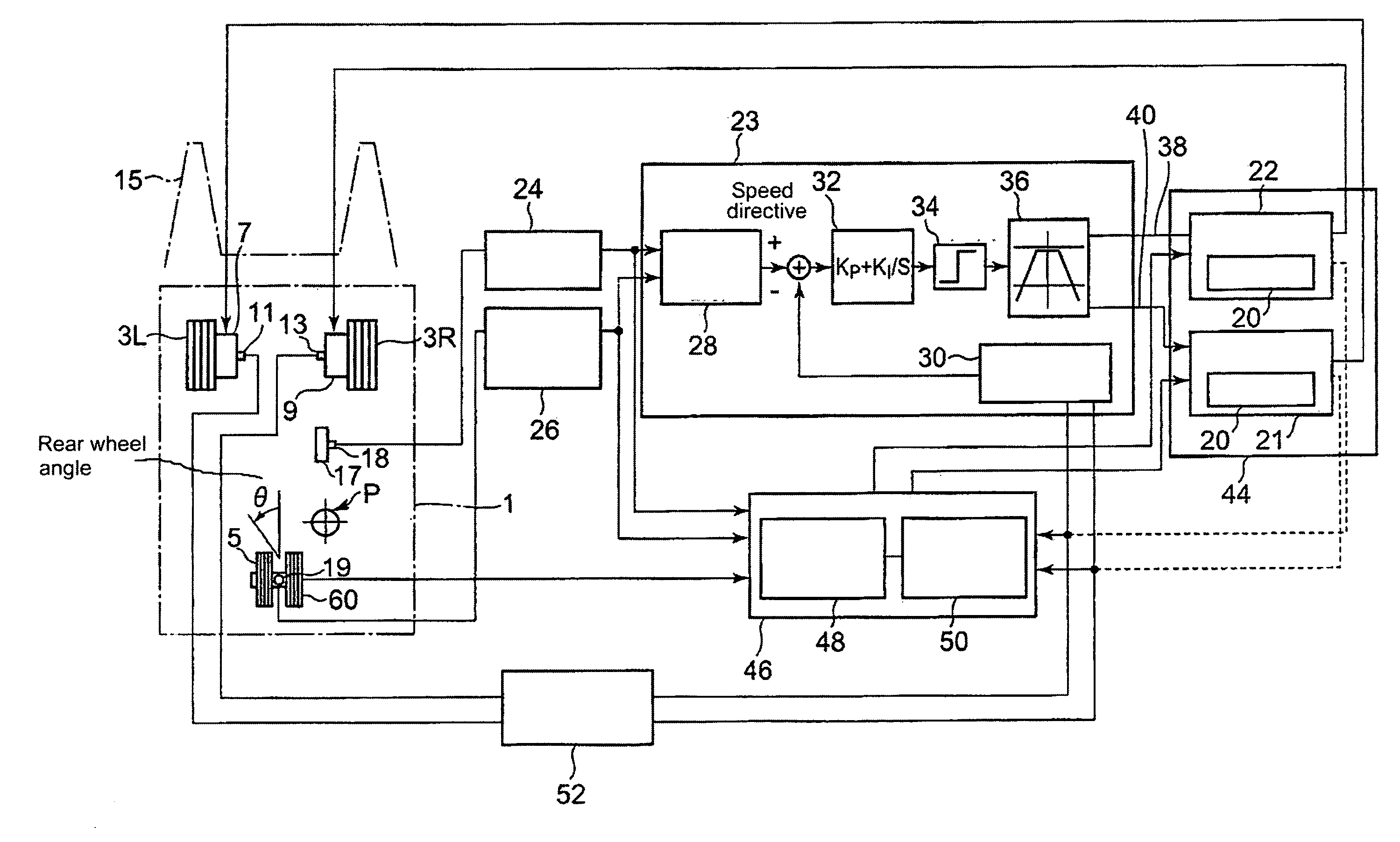
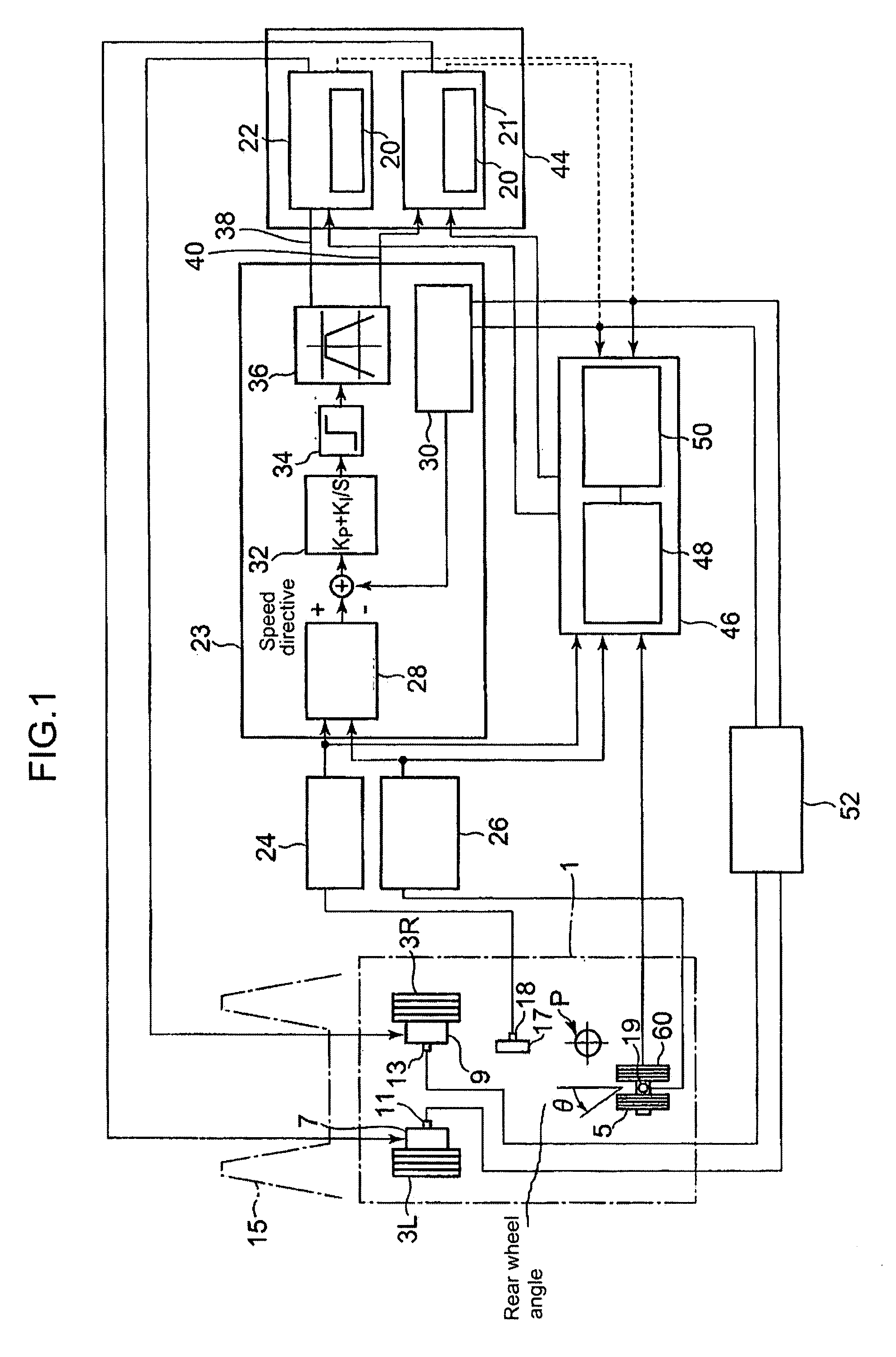
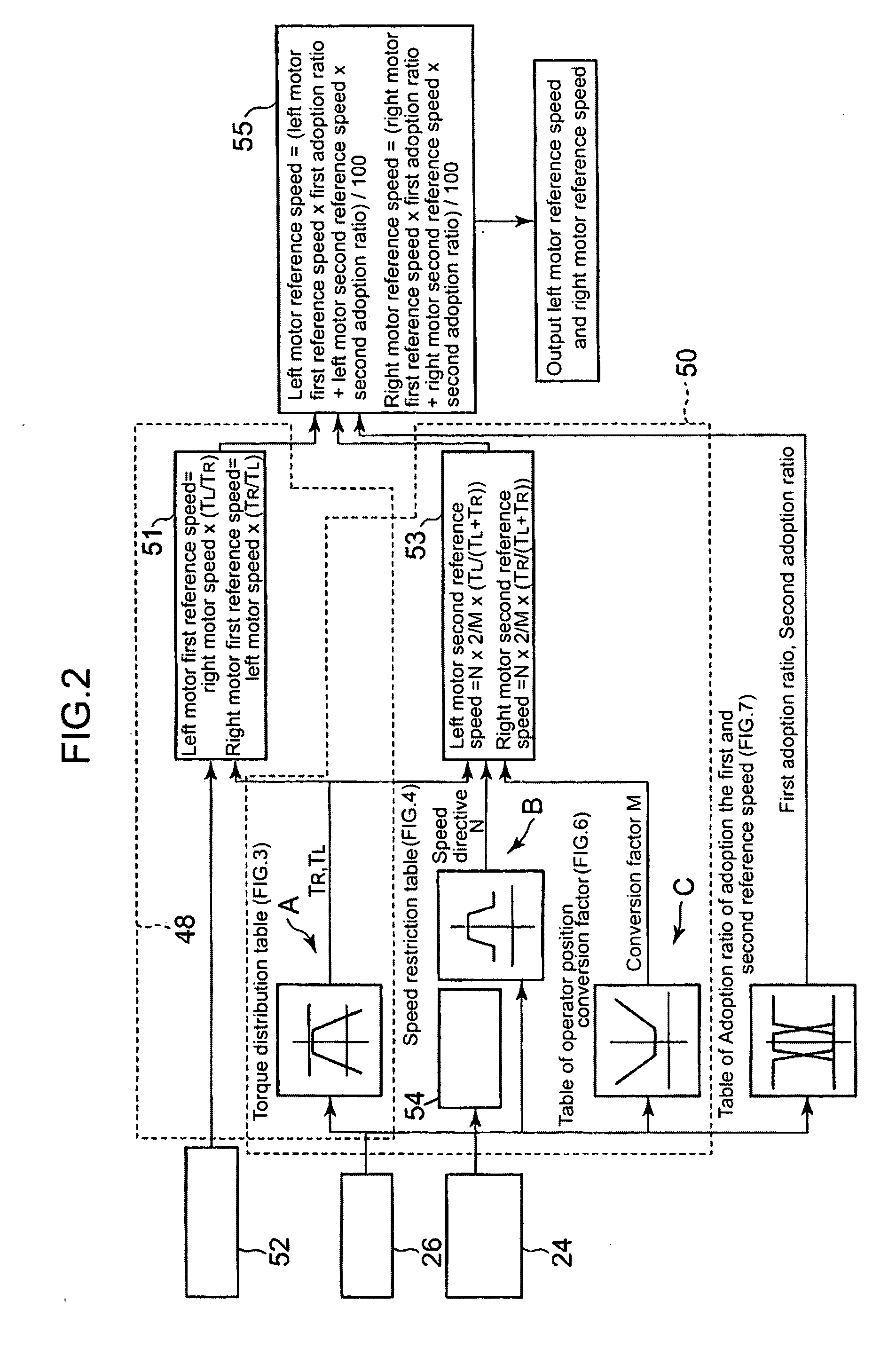
[0046]FIG. 1 is a representation of schematic configuration of the electric vehicle and slip control device thereof of the invention. FIG. 2 is a block diagram of the reference speed calculation means in the slip control device. FIG. 3 is a diagram showing torque admeasurement characteristic for right and left wheels. FIG. 4 are drawings for explaining the first reference speed calculation means, FIG. 4a shows when straight-ahead driving, and FIG. 4b shows when turning to the right at 50 degrees. FIG. 5 is a diagram showing characteristic of speed limiter. FIG. 6a is a characteristic curve of operator position conversion factor, and FIG. 6b is a drawing for explaining the conversion factor.

[0047]FIG. 7 is a diagram showing adoption ratio of the first and second speed calculation means. FIG. 8 is a flowchart of process of putting restriction to reference speed ...


PUM


Abstract

A slip control device, a slip control method, and a vehicle provided with such a slip control device are provided, with which the vehicle can travel stably even on a slippery road surface maintaining good road holding. The device is provided with a torque directive control means (23) for calculating torque directives for the motors respectively based on acceleration pedal depressions (24) and steering angles (26) and outputting them to each of motor control sections (21, 22) of the motors, a first reference speed calculation means (48) for calculating first reference speed of one of the pair of left and right motors to be controlled based on rotation speed of the other motor of the pair of motors, and a restriction putting means (20) for putting restriction to each of the torque directives sent from the torque directive control means (23) based on a permissible speed range determined for each of the motors by putting prescribed permissible speed deviation to each of the calculated reference speeds.

Description

BACKGROUND OF THE INVENTION[0001]1. Field of the Invention[0002]The present invention relates to a slip control device for suppressing occurrence of slip of driving wheels, a slip control method, and an electric vehicle installed with the control device, the electric vehicle having a pair of right and left wheels driven independently by an electric motor respectively.[0003]2. Description of the Related Art[0004]In a vehicle driven with an engine, right and left driving wheels are connected via a differential and composed such that situations like only the load on the wheel of one side is reduced or slips alone will not happen.[0005]However, in recent years, electric vehicles of light weight and high performance with individual electric motor attached to each driving wheel are prevailing. There is a problem in those electric vehicles that, since the right and left wheel are driven independently, when the load on the wheel of one side decreases or the friction coefficient of the wheel...

Claims


Application Information

Patent Timeline
Patent Type & Authority Applications(United States)
IPC IPC(8): B61C15/08
CPCB60K7/0007Y02T10/7275B60L3/102B60L11/00B60L15/2036B60L2200/42B60L2220/44B60L2240/24B60L2250/26B60W2520/266B60W2540/10B60W2720/28B60Y2200/15Y02T10/646Y02T10/648B60K28/16Y02T10/72B60L50/00Y02T10/64B60W2540/18
Inventor NAKAMURA, MITSUGUNAKAKITA, OSAMUIWAMOTO, YOSHIHIDENAKAO, ATSUSHI
Owner NIPPON YUSOKI
Why Eureka
Try Eureka