
Method for recognizing a shape from a path of a digitizing device

Inactive Publication Date: 2009-01-29
TUFTS UNIV
View PDF8 Cites 40 Cited by
  • Summary
  • Abstract
  • Description
  • Claims
  • Application Information

AI Technical Summary

Benefits of technology

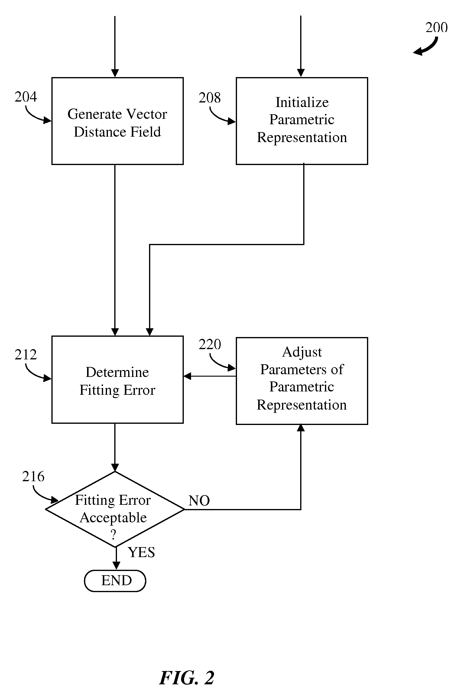
[0026]In another aspect, the invention features a computer program product for recognizing a shape from a path of a digitizing device. The computer program product includes a computer useable medium having embodied therein program code. The program code includes program code for acquiring a set of digitized points along a path of a digitizing device, program code for fitting a parametric representation to the path of the digitizing device and program code for comparing the parametric representation to a set of known shapes to recognize that the path of the digitizing device represents a particular shape in the set of known shapes. Fitting includes generating a vector distance field representation of a set of objects corresponding to the set of digitized points, initializing a parametric representation to fit the set of objects, determining a fitting error from the vector distance field representation and adjusting the parametric representation to reduce the fitting error.

Problems solved by technology

The fitting error indicates an accuracy of the fit of the parametric representation to the set of objects.

Method used


Image

  • Method for recognizing a shape from a path of a digitizing device
  • Method for recognizing a shape from a path of a digitizing device
  • Method for recognizing a shape from a path of a digitizing device

Examples


first embodiment

[0052]In a first embodiment, a piecewise polynomial estimating curve composed of two-dimensional cubic Bezier curve segments is fit to a sequence of digitized points representing a path of a digitizing device on-the-fly, i.e., as each digitized point is provided to the application. In this embodiment, the digitized points are recorded using a two-dimensional input device such as a computer mouse or a digital pen, or a three-dimensional input device such as a force feedback device or a three-dimensional tracking device.

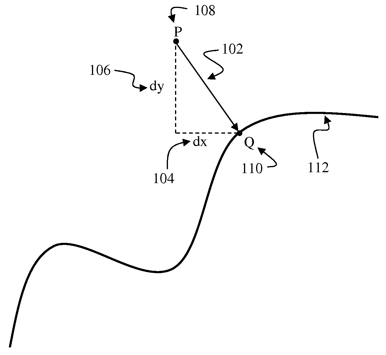
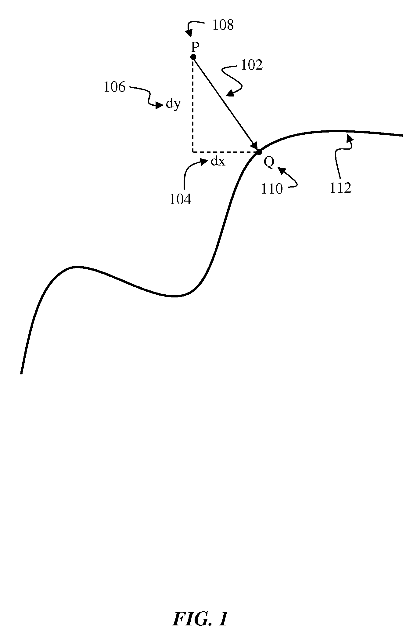
[0053]Standard curve fitting approaches measure a distance from each digitized point to the estimating curve, which requires finding a closest point on the estimating curve for each digitized point each time parameters of the estimating curve are adjusted. FIG. 3A illustrates the closest points Qi 311, 312, . . . , 319 (generally Q) on the estimating curve 300 corresponding to each sample point Pi 301, 302, . . . , 309 (generally P) of the object. As illustrated in FIG...

second embodiment

[0094]A second step of the second embodiment is to initialize a parametric surface representation to approximate the set of digitized points. There are various approaches for initializing the parametric surface. For example, a user can construct an initial parametric surface composed of a set of coarse surface patches using a drawing application or computer aided design system. As a second example, the parametric surface can be automatically initialized as a minimal bounding sphere surrounding the digitized points. As a third example, the parametric surface can be initialized to be a coarse triangular mesh that is generated either automatically or semi-automatically to approximate the surface.

[0095]A third step of the second embodiment is to iteratively adjust parameters of the parametric surface, where the adjustment is responsive to a fitting error between the parametric surface and the set of digitized points using the vector distance field. Parameters of the parametric surface a...

fourth embodiment

[0103]the method of the invention determines a medial axis of a two-dimensional closed outline, where the medial axis is composed of a set of piecewise polynomial segments.

[0104]In a first step, a two-dimensional adaptively sampled vector distance field of the closed outline is generated, where the adaptive sampling rate is higher near the medial axis of the closed outline. In a second step, cells of the adaptively sampled vector distance field that are inside the closed outline and that contain the medial axis are determined. There are various ways to determine cells that contain the medial axis from the vector distance field. For example, the directions of vector distances at the corner vertices of a cell containing the medial axis are substantially different. Alternatively, the divergence of the vector distance field within a cell containing the medial axis is substantially greater than zero. The divergence of the vector distance field can be determined from the partial derivativ...


PUM


Abstract

Described is a method for recognizing a shape from a path of a digitizing device. A set of points along a path of the digitizing device is acquired and a parametric representation is fit to the path. The parametric representation is compared to a set of known shapes to determine that the path of the digitizing device represents a particular shape. Fitting the parametric representation to the path includes generating a vector distance field representation of a set of objects corresponding to the set of digitized points, initializing a parametric representation to fit the set of objects, determining a fitting error from the vector distance field representation and adjusting the parametric representation to reduce the fitting error. The fitting error indicates an accuracy of the fit of the parametric representation to the set of objects.

Description

FIELD OF THE INVENTION[0001]The invention relates generally to fitting a parametric representation to a digital representation of an object. More particularly, the invention relates to a method using a vector distance field representation of a set of objects to determine a parametric representation of the set of objects.BACKGROUND OF THE INVENTION[0002]Fitting Parametric Surfaces to Digital Data[0003]Digital data such as a set of positions recorded from a digital input device, a set of curves representing a character glyph, or a set of experimental measurements, can be fit with a parametric representation that approximates the shape of the digital data to reduce memory requirements for storing and transmitting the digital data or to facilitate processing of the digital data.[0004]For example, when drawing via a computer mouse or digital pen, the path of the input device is sampled, the sampled points are typically quantized to integer pixel locations, and these digitized points are ...

Claims


Application Information

Patent Timeline
IPC IPC(8): G06T11/20
CPCG06T11/203G06K9/00409G06V30/333
Inventor FRISKEN, SARAH F.
Owner TUFTS UNIV
Learn More