Lighting fixture

a technology of light fixture and reflection surface, which is applied in the direction of fixed installation, lighting and heating apparatus, lighting support devices, etc., can solve the problems of not being able to illuminate brightly at a wide angle unable to achieve wide angle illumination in the longitudinal direction of the lighting fixture, and not being able to achieve bright illumination near the lighting fixture. , to achieve the effect of enhancing the emission intensity of light storage material, reducing the possibility of reflected

Inactive Publication Date: 2009-01-29
STANLEY ELECTRIC CO LTD +1
View PDF9 Cites 14 Cited by
  • Summary
  • Abstract
  • Description
  • Claims
  • Application Information

AI Technical Summary

Benefits of technology

[0036]In other words, in the lighting fixture, the light-storage material is not placed all over the reflection surface, but there remains a part where the light-storage material is not placed. Therefore, a reflection ratio of the reflection surface can be improved as compared to the case where the light-storage material is placed over the entire surface, thereby reducing the possibility that the reflected light from the reflection surface is weakened when the LED is turned ON. In other words, the lighting fixture can enable illumination by the auxiliary light when the LED is OFF, therefore reducing the possibil

Problems solved by technology

As a result, this lighting fixture allows illumination from the light emitting device modules at a wide angle in the lateral direction of the lighting fixture, but it is not capable of illuminating at a wide angle in the longitudinal direction of the lighting fixture.
Therefore, if a position close to the lighting fixture in the front sid

Method used


Image

  • Lighting fixture
  • Lighting fixture
  • Lighting fixture

Examples


first embodiment

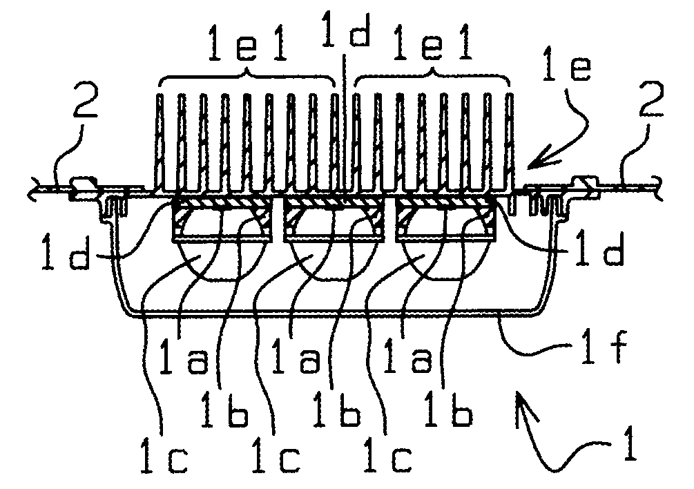
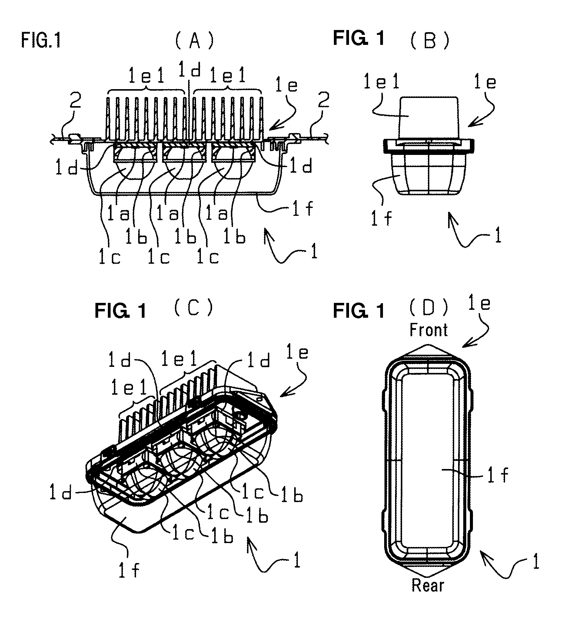
[0055]FIG. 1 illustrates a light emitting device module 1 which constitutes a part of a lighting fixture made in accordance with principles of the disclosed subject matter. In more detail, FIG. 1(A) is a left side view of the light emitting device module 1, which is partially illustrated as a sectional view, FIG. 1(B) is a front view of the light emitting device module 1, FIG. 1(C) is a perspective view from the front, left and lower side, and FIG. 1(D) is a bottom view of the light emitting device module 1.

[0056]In FIG. 1, the reference numeral 1a indicates a light emitting device such as an LED, for instance. The reference numeral 1b indicates a reflector being provided with a reflection surface for reflecting the light emitted from the light emitting device 1a downwardly (toward the lower side in FIG. 1(A) and FIG. 1(B)). The reference numeral 1c indicates a lens mounted on the reflector 1b for controlling a light distribution of the light emitted directly from the light emitting...

fifth embodiment

[0094]FIG. 7 illustrates enlarged views of the light emitting device (LED package) 1a, the reflector 1b, and the thermal interface material 1d of the lighting fixture 10 according to the FIG. 7(A) is an enlarged sectional front view of the light emitting device (LED package) 1a, the reflector 1b, and the thermal interface material 1d. FIG. 7 (B) is a bottom view thereof, i.e., it is an illustration when viewing the illustration of FIG. 7(A) from the lower side.

[0095]In the lighting fixture of the fifth embodiment, as shown in FIG. 7(A) and FIG. 7(B), there are provided on the reflection surface 1b1 of the reflector 1b, a part 1b1a where a light-storage material is placed and a part 1b1b where the light-storage material is not placed. In more detail, the light-storage material can be applied in the form of mesh on the reflection surface 1b1 of the reflector 1b, thereby forming the part 1b1a where the light-storage material is placed. Furthermore, the light-storage material can be ap...

sixth embodiment

[0109]As shown in FIG. 8(A) and FIG. 8(B), in the lighting fixture of the sixth embodiment, there are provided on the reflection surface 1b1 of the reflector 1b a part 1b1a where the light-storage material is placed and a part 1b1b where the light-storage material is not placed.

[0110]Specifically, in the lighting fixture of the fifth embodiment, as shown in FIG. 7(A) and FIG. 7(B), the light-storage material is applied in the form of mesh on the reflection surface 1b1 of the reflector 1b, thereby forming the part 1b1a where the light-storage material is placed. Alternatively, in the sixth embodiment, as shown in FIG. 8(A) and FIG. 8(B), the light-storage material is applied in the form of dots on the reflection surface 1b1 of the reflector 1b, thereby forming the part 1b1a on which the light-storage material is placed.

[0111]FIG. 9 illustrates enlarged views of the light emitting device (LED package) 1a, the reflector 1b, the thermal interface material 1d, and the like, of the lighti...


PUM


Abstract

Light emitting device modules illuminate at a wide angle in the longitudinal direction of a lighting fixture. The lighting fixture can be provided with a light emitting device module having a light emitting device, an installation member for mounting multiple light emitting device modules thereon, and a support for supporting the installation member. The installation member 2 can be bent in multiple stages so that light beams from the multiple light emitting device modules mounted on the installation member are pointed to multiple different directions. The installation member can be bent in multiple stages so that an angle between the main optical axis line of the light emitting device module mounted on the forefront part of the installation member and a horizontal plane is smaller than the angle between the main optical axis line of the light emitting device module mounted on the root part of the installation member and the horizontal plane.

Description

[0001]This application is a continuation under 35 U.S.C. §120 of PCT Patent Application No. PCT / JP2007 / 52859, filed on Feb. 16, 2007, which also claims the priority benefit of Japanese Patent Application Nos. 2006-041867 (filed on Feb. 20, 2006) and 2006-050614 (filed on Feb. 27, 2006), which are hereby incorporated in their entireties by reference.BACKGROUND[0002]1. Technical Field[0003]The disclosed subject matter relates to a lighting fixture having an installation member which is bent in multiple stages, and in such a manner that light beams from multiple light emitting device modules mounted on the installation member are pointed in multiple different directions, respectively.[0004]2. Description of the Related Art[0005]The lighting fixture described in Japanese Published Unexamined Patent Application No. 2004-200102, for example, is equipped with a light emitting device module having a light emitting device, an installation member for mounting multiple light emitting devices, ...

Claims


Application Information

Patent Timeline
IPC IPC(8): F21V5/04F21S4/00
CPCF21S8/086F21V7/22F21V9/16F21V19/001F21V29/74F21Y2101/02F21V7/0066Y10S362/80F21V29/507F21W2131/103F21V9/08F21Y2115/10F21V7/24F21V9/30
Inventor KOIKE, TERUOBANBA, SHOICHITSUKADA, KATSURAYAMADA, MITSUONAGASAWA, SATOSHI
Owner STANLEY ELECTRIC CO LTD
Why Eureka
Try Eureka