
Systems, compositions, and methods for local imaging and treatment of pain

Active Publication Date: 2009-01-29
RGT UNIV OF CALIFORNIA
View PDF21 Cites 112 Cited by
  • Summary
  • Abstract
  • Description
  • Claims
  • Application Information

AI Technical Summary

Benefits of technology

[0015]In addition to the significant benefit provided by these approaches for clinical diagnosis, they are also considered highly beneficial in providing new avenues to drive choices for therapeutic approaches.
[0269]According to another mode of the present aspect, the method further comprises imaging a location of the targeted agent bound to the pain factor in a manner allowing for enhanced localized therapy to the location.

Problems solved by technology

However, such measures are often not specific enough to localize the exact site in or around a degenerating disc where pain is being experienced.
Also, a direct correspondence is not always found between disc degeneration and back pain.
Consequently, existing imaging modalities that identify (and even quantify) disc anatomy, such as CT or MRI, are not always helpful at localizing sources of back pain in many cases.

Method used


Image

  • Systems, compositions, and methods for local imaging and treatment of pain
  • Systems, compositions, and methods for local imaging and treatment of pain
  • Systems, compositions, and methods for local imaging and treatment of pain

Examples


Embodiment Construction

[0297]Referring more specifically to the drawings, for illustrative purposes the present invention is embodied in the systems and methods generally shown in or illustrated by reference to FIG. 1 through FIG. 8. It will be appreciated that the apparatus may vary as to configuration and as to details of the parts, and that the method may vary as to the specific steps and sequence, without departing from the basic concepts as disclosed herein.

[0298]Label Disc Features Associated with Pain

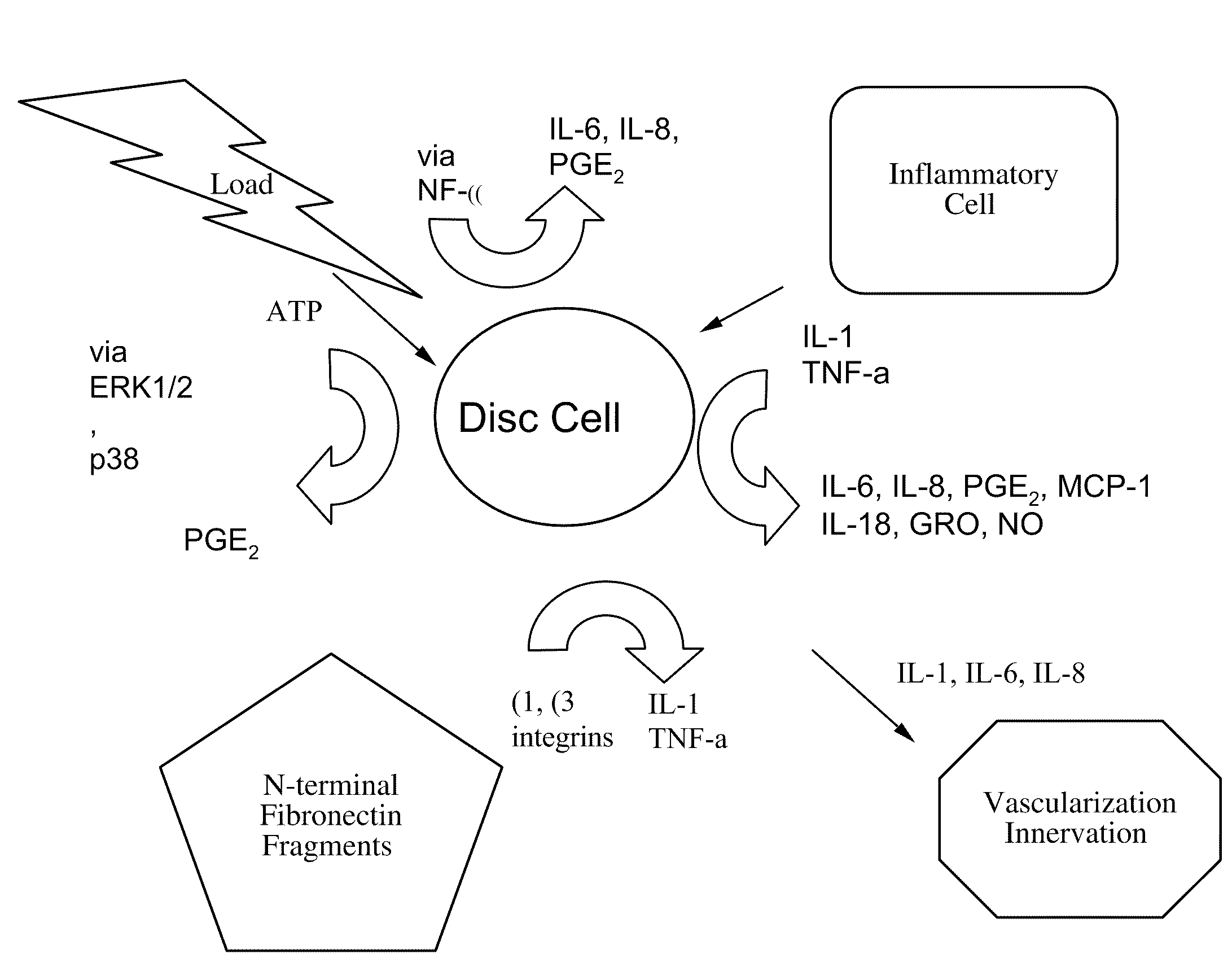
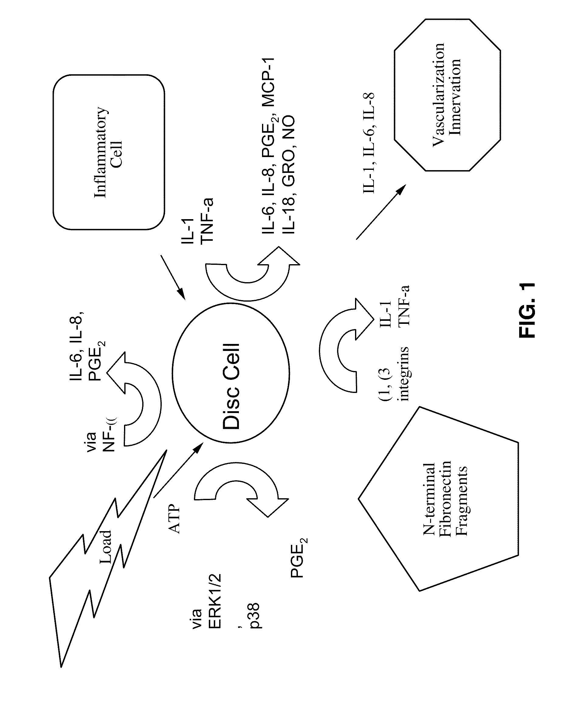
[0299]Discogenic pain is generally believed to be a multifactoral phenomenon in many cases. In particular, three illustrative factors are summarized in varying levels of detail here as examples that are considered contributors in various ways to (or otherwise indicative of) the generation or transmission of discogenic pain. It is believed that these illustrative factors frequently act as a co-existent combination, often acting simultaneously. These types of factors are summarized as follows.

[0300]One s...


PUM

PropertyMeasurementUnit
Concentrationaaaaaaaaaa
Structureaaaaaaaaaa
Volumeaaaaaaaaaa

Abstract

Pain factors are labeled with targeted agents or markers delivered into the body. The labeled pain factors are imaged with appropriate imaging tools in a manner allowing selective identification and localization of areas of pain source or transmission. The labeled pain factors allow spatial differentiation in the imaging sufficient to specify the location of the pain so as to drive therapeutic decisions and techniques in order to treat the pain. Pain factors labeled and imaged in this manner may include one or more of nerve factors, blood vessel factors, cellular factors, and inflammation factors. Labeled markers may include for example radioactive materials (e.g. tritiated or iodinated molecules) or other materials such as metal (e.g. gold) nanoparticles. Intermediary binding materials may be used, such as for example bi-specific antibodies. Therapeutic components of the system and method include for example localized energy delivery or ablation treatments, or local drug or other chemical delivery. Locations containing pain factor selectively bound by targeted agents are selectively treated with directed energy into a region containing the targeted agent bound to the pain factor.

Description

CROSS-REFERENCE TO RELATED APPLICATIONS[0001]This patent application claims priority from, and is a 35 U.S.C. § 111(a) continuation of, co-pending PCT international application serial number PCT / US2006 / 036943, filed on Sep. 21, 2006, incorporated herein by reference in its entirety, which claims priority from U.S. Provisional Patent Application Ser. No. 60 / 719,670 filed on Sep. 21, 2005, incorporated herein by reference in its entirety, and from U.S. Provisional Patent Application Ser. No. 60 / 750,990 filed on Dec. 15, 2005, incorporated herein by reference in its entirety.[0002]This application is also related to PCT Publication number WO 2007 / 035906, published Mar. 29, 2007, incorporated herein by reference in its entirety.STATEMENT REGARDING FEDERALLY SPONSORED RESEARCH OR DEVELOPMENT[0003]Not ApplicableINCORPORATION-BY-REFERENCE OF MATERIAL SUBMITTED ON A COMPACT DISC[0004]Not ApplicableNOTICE OF MATERIAL SUBJECT TO COPYRIGHT PROTECTION[0005]A portion of the material in this pate...

Claims


Application Information

Patent Timeline
IPC IPC(8): A61B18/18A61K101/02A61K51/10A61K49/00A61N7/00A61B6/00A61K49/22A61K49/06A61B18/08
CPCA61B5/4824A61B6/506A61N7/02A61K49/0002A61P19/00A61P19/02A61P21/00A61P25/00A61P29/00A61B5/4041A61B18/14A61B2018/00339A61B2018/00577A61B2018/00642A61K51/1096A61M5/007A61M5/1723A61M2230/005
Inventor BRADFORD, DAVID S.LOTZ, JEFFREY C.
Owner RGT UNIV OF CALIFORNIA
Learn More