Ultrasonic curved blade

a technology of ultrasonic blades and curved blades, applied in the field of ultrasonic instruments, can solve the problems of limited movement of instruments, and achieve the effect of enhancing conta

Inactive Publication Date: 2009-01-29
TYCO HEALTHCARE GRP LP
View PDF2 Cites 10 Cited by
  • Summary
  • Abstract
  • Description
  • Claims
  • Application Information

AI Technical Summary

Benefits of technology

[0008]In accordance with the present disclosure, an ultrasonic system for dissection and coagulation of tissue is provided. The system includes an ultrasonic instrument, a control module, and a remote actuator. The ultrasonic instrument has a housing and an elongated body portion extending from the housing. An ultrasonic transducer supported within the housing is operatively connected to a cutting jaw by a vibration coupler. The vibration coupler conducts high frequency vibration from the ultrasonic transducer to the cutting jaw. The cutting jaw has a blade surface which is curved outwardly and downwardly along its surface and thus, curved with respect to the axis of vibration. The curved blade surface is preferably configured such that the angle defined between a line tangent to the blade surface and the longitudinal axis of the elongated body portion varies from about 5 degrees to about 45 degrees along the length of the blade surface. A clamp member having a tissue contact surface is positioned adjacent to the cutting jaw and is movable from an open position in which the tissue contact surface is spaced from the blade surface to a clamped position in which the tissue contact surface is in close juxtaposed alignment with the blade surface to clamp tissue therebetween. The clamp member and the angled blade combine to enhance contact between tissue and the blade surface of the blade member.

Problems solved by technology

During an endoscopic procedure, movement of the instrument is limited to movement along an axis parallel to the plane of the clamping region.

Method used


Image

  • Ultrasonic curved blade
  • Ultrasonic curved blade
  • Ultrasonic curved blade

Examples


Embodiment Construction

[0029]Preferred embodiments of the presently disclosed ultrasonic dissection and coagulation system will now be described in detail with reference to the drawings, in which like reference numerals designate identical or corresponding elements in each of the several views.

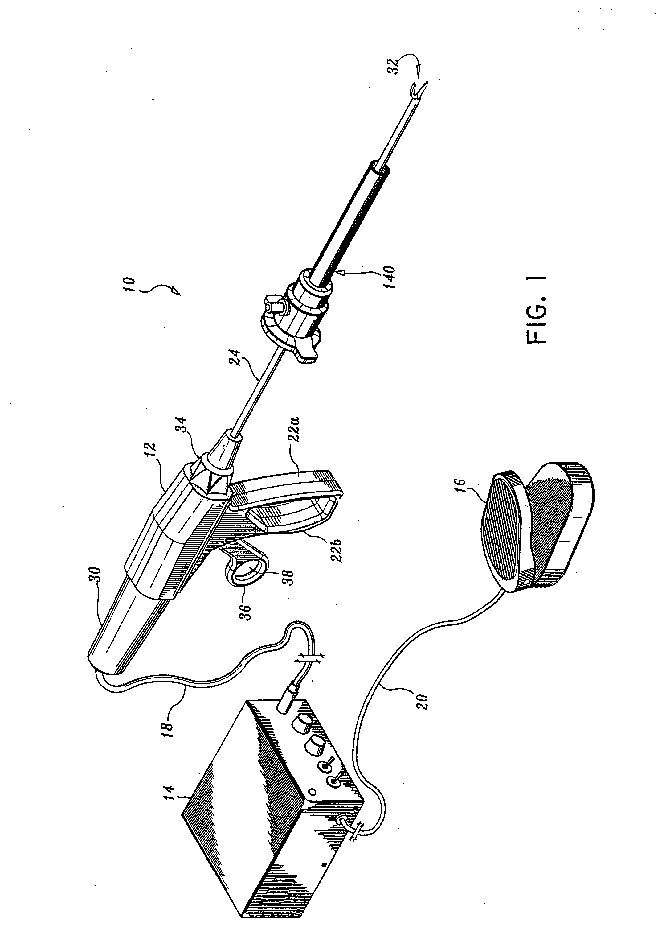
[0030]FIG. 1 illustrates the ultrasonic dissection and coagulation system shown generally as 10. Briefly, dissection and coagulation system 10 includes ultrasonic instrument 12, control module 14, and remote actuator 16. Control module 14 is operatively connected to ultrasonic instrument 12 by electrically conductive cable 18 and functions to control the power and frequency of current supplied to ultrasonic instrument 12. Any suitable controller capable of delivering power to ultrasonic instrument 12 can be used. Control module 14 does not form part of the invention and will not be further discussed herein. Remote actuator 16, e.g., pedal actuator, is operatively connected to control module 14 by electrically conduc...


PUM


Abstract

An ultrasonic dissection and coagulation system for surgical use is provided. The system includes an ultrasonic instrument, a control module, and a remote actuator. The ultrasonic instrument has a housing and an elongated body portion extending from the housing. An ultrasonic transducer supported within the housing is operatively connected to a cutting jaw by a vibration coupler. The vibration coupler conducts high frequency vibration from the ultrasonic transducer to the cutting jaw. The cutting jaw has a blade surface which is curved downwardly and outwardly in the distal direction with respect to the longitudinal axis of the elongated body portion along its length such that an angle defined by a line drawn tangent to the blade surface and the longitudinal axis of the elongated body portion varies between 5 degrees and 75 degrees. A clamp member having a tissue contact surface is positioned adjacent to the cutting jaw and is movable from an open position in which the tissue contact surface is spaced form the blade surface to a clamped position in which the tissue contact surface is in close juxtaposed alignment with the blade surface to clamp tissue therebetween. The clamp member and the curved cutting jaw combine to enhance contact between tissue and the blade surface of the cutting jaw during cutting. Further, the continuously varying angle of the blade surface with respect to the longitudinal axis of the elongated body portion facilitates selective user control over the application of force on tissue during a cutting or dissecting procedure.

Description

CROSS REFERENCE TO RELATED APPLICATION[0001]This application is a continuation of U.S. patent application Ser. No. 10 / 241,936, filed Sep. 11, 2002, which is a continuation of U.S. patent application Ser. No. 09 / 604,877, filed Jun. 28, 2000, which is a continuation of U.S. patent application Ser. No. 09 / 420,640, filed Oct. 20, 1999, which is a continuation of U.S. patent application Ser. No. 08 / 911,205, filed Aug. 14, 1997, now U.S. Pat. No. 6,024,750, all of which are incorporated herein by reference.BACKGROUND[0002]1. Technical Field[0003]The present disclosure relates to an ultrasonic dissection and coagulation system for surgical use. More specifically, the present disclosure relates to an ultrasonic instrument including a curved blade and a clamp member particularly suited for performing dissection and coagulation of tissue.[0004]2. Background of Related Art[0005]Ultrasonic instruments for surgical use and the benefits associated therewith are well known. For example, the use of...

Claims


Application Information

Patent Timeline
Patent Type & Authority Applications(United States)
IPC IPC(8): A61B17/32A61B17/28
CPCA61B17/29A61B17/295A61B2017/320072A61B2017/2825A61B17/320092A61B2017/320094A61B2017/320075A61B2017/320095
Inventor MASTRI, DOMINICK L.STONE, CORBETT W.
Owner TYCO HEALTHCARE GRP LP
Why Eureka
Try Eureka