System and Method for Tensioning an Emergency Brake System

a technology of emergency brake system and system, which is applied in the direction of apparatus for force/torque/work measurement, wire tools, instruments, etc., can solve the problems of limited measurement accuracy, relative cost, and the typical measurement of cable system tension by indirect methods

Active Publication Date: 2009-02-05
PETRAK GREGORY H
View PDF60 Cites 21 Cited by
  • Summary
  • Abstract
  • Description
  • Claims
  • Application Information

AI Technical Summary

Benefits of technology

[0011]A method of practicing the invention is described herein and includes tensioning a brake system on a vehicle comprising the acts of inserting a cable end into a tool, manually actuating a locking mechanism to engage the cable end to establish a tensioning condition, tensioning the cable, and manually deactuating the locking mechanism to disengage the cable from the tool. Further to this method, the manually actuating step creates a rigid mechanical column against which to measure tension in the cable.

Problems solved by technology

The existing systems require more than one assembly worker and more than one station, and thus are a relatively expensive endeavor.
A further limitation of the existing brake cable system installation technology is that the tension in the cable system is typically measured by indirect methods, such as strain gauges and other types of transducers.
This indirect tension measurement has limited measurement accuracy, and thus causes there to be a relatively wide variation in the ultimate tension at which the emergency brake cable system is assembled in a vehicle.
This creates unwanted variations in the emergency brake cable system operation on the finished vehicle.
However, these systems use hydraulics or pneumatics as part of the process, which may lead to maintenance problems, cleanliness issues, tension measurement inaccuracies, and generally to a more complicated and inconvenient system.

Method used


Image

  • System and Method for Tensioning an Emergency Brake System
  • System and Method for Tensioning an Emergency Brake System
  • System and Method for Tensioning an Emergency Brake System

Examples


Embodiment Construction

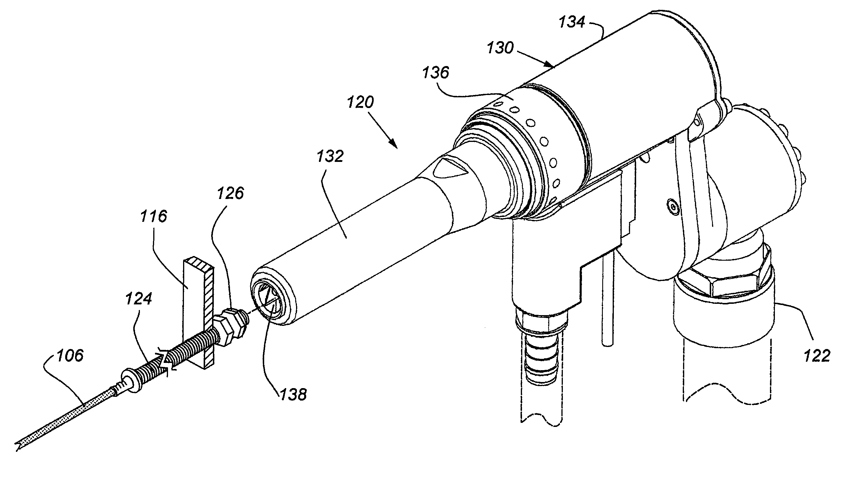
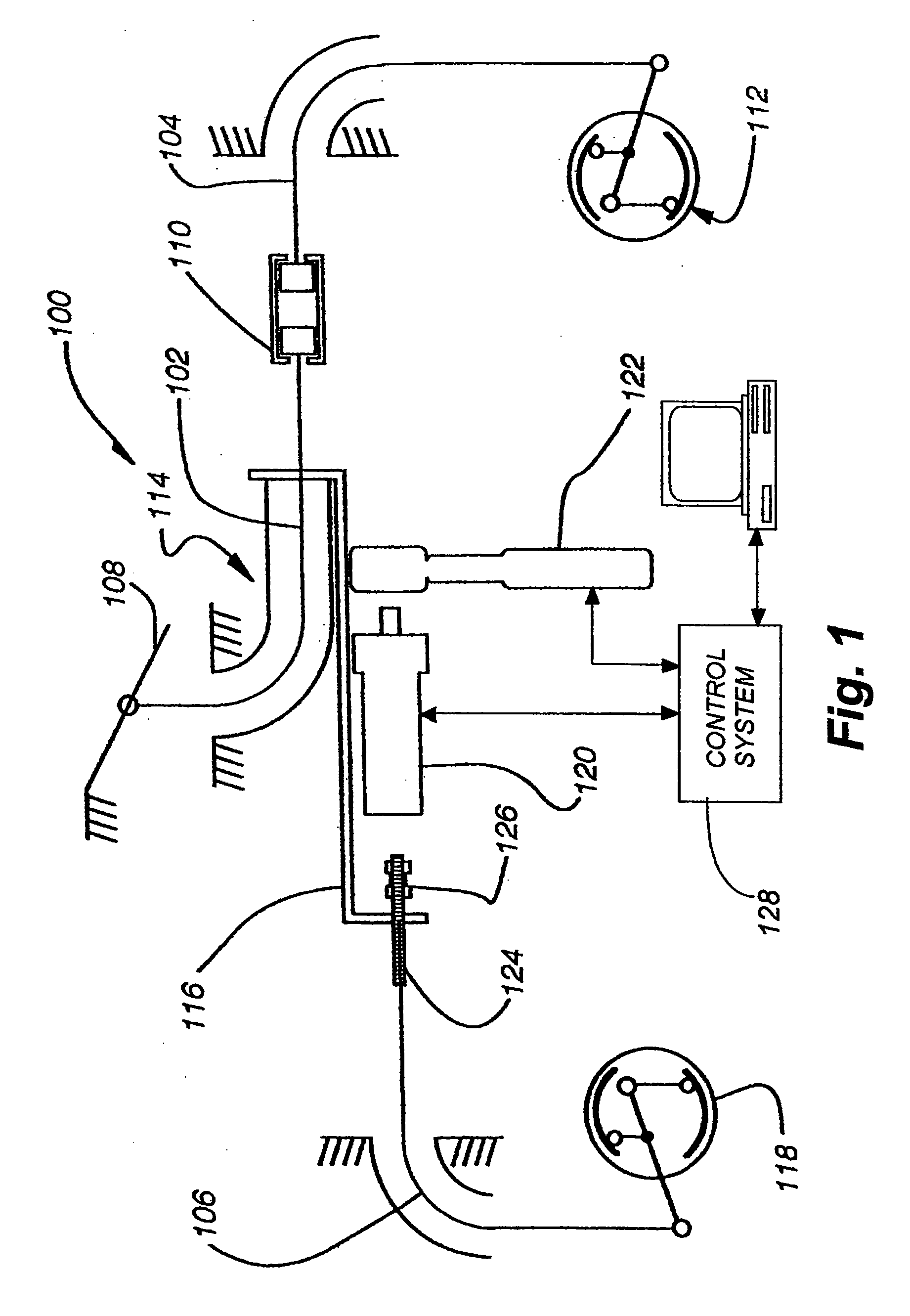
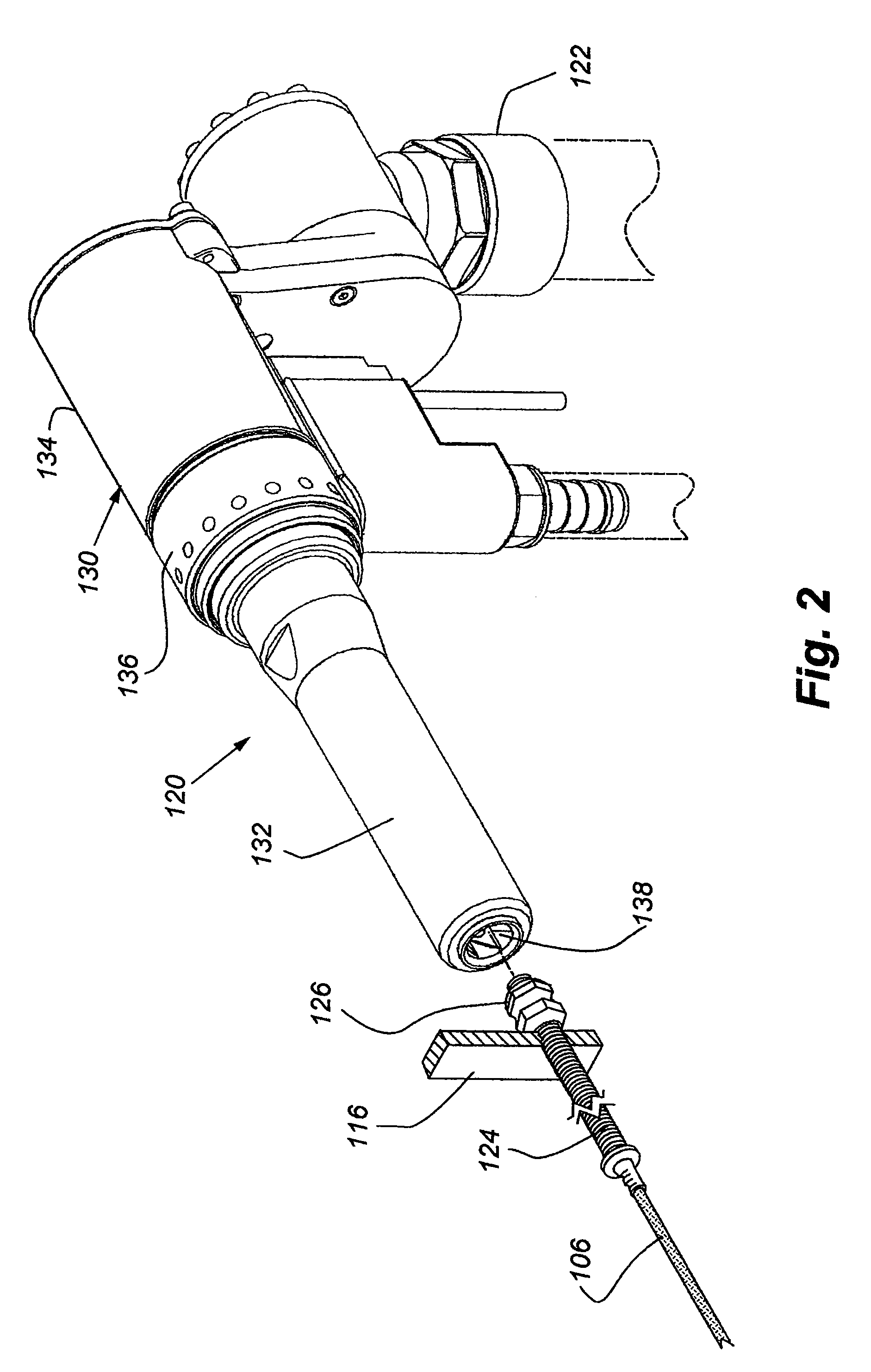
[0024]The instant invention is embodied in a tensioning apparatus attachment to a drive tool, such as a ratchet, nut runner, or other type of wrench, used for tensioning the park brake cable system of an automobile during assembly. A schematic of one embodiment of the present invention and the system in which it works is shown in FIG. 1. FIG. 1 illustrates a side pull park brake system 100. In the park brake system 100 in which this invention is described, there is a front cable 102, a rear right cable 104 and a rear left cable 106. The front cable 102 is attached to a pull handle 108 at its first end and at its second end it is attached to a connector clip 110, which in turn attaches to the front end of the rear right cable 104. The rear right cable extends towards and attaches to the brake assembly 112 on the rear right wheel. The front cable 102 and the rear right cable 104 could be one continuous cable, however, it has been found more convenient to have them be separate cables f...


PUM

PropertyMeasurementUnit
tensionaaaaaaaaaa
tension measuringaaaaaaaaaa
ultimate tensionaaaaaaaaaa

Abstract

A brake tensioning system and method are described herein for use on vehicles. The system includes a tool, and the method includes the use of the tool to effectuate tensioning of a brake system conveniently, accurately, and repeatably.

Description

RELATED APPLICATIONS[0001]This application claims the benefit under 35 U.S.C. § 119(e) to U.S. Provisional Patent Application No. 60 / 953,185, filed Jul. 31, 2007, and entitled “System and Method for Tensioning a Brake System,” which is incorporated by reference as if fully disclosed herein. This application also incorporates by reference U.S. patent application Ser. No. 10 / 369,989, filed Feb. 18, 2003, and entitled “Method and Apparatus for Tensioning an Emergency Brake System on a Vehicle,” now U.S. Pat. No. 7,331,255; and U.S. patent application Ser. No. 10 / 254,050, filed Sep. 23, 2002, and entitled “Method and Apparatus for Tensioning an Emergency Brake System on a Vehicle,” now U.S. Pat. No. 7,331,254, both of which are incorporated by reference as if fully disclosed herein.FIELD OF THE INVENTION[0002]This invention relates to apparatus and methods associated with the tensioning of an emergency brake system on a vehicle, and more particularly to an end effector that receives a n...

Claims


Application Information

Patent Timeline
Patent Type & Authority Applications(United States)
IPC IPC(8): B25B25/00B60T1/00F16C1/22G01L1/04
CPCY10T74/20408B60T13/746
Inventor PETRAK, GREGORY H.
Owner PETRAK GREGORY H
Why Eureka
Try Eureka