
Inflatable mirage kayak

a technology of inflatable watercraft and mirage, which is applied in the field of inflatable watercraft propelled by humans, can solve the problems of difficult storage in a garage, on a large boat or in a motor home, and the need for considerable storage spa

Active Publication Date: 2009-02-05
HOBIE CAT IP LLC
View PDF31 Cites 35 Cited by
  • Summary
  • Abstract
  • Description
  • Claims
  • Application Information

AI Technical Summary

Benefits of technology

[0031]FIG. 19 is a perspective view of a cut out and removed area of one of the inflatable portions of the watercraft of this invention, in the inflated state.

Problems solved by technology

Because they are rigid, considerable space is required for storage when the kayak is not in use and they are generally difficult to store in a garage, on a large boat or in a motor home due to it large size.

Method used


Image

  • Inflatable mirage kayak
  • Inflatable mirage kayak
  • Inflatable mirage kayak

Examples


Embodiment Construction

[0046]Turning to the drawings in more detail.

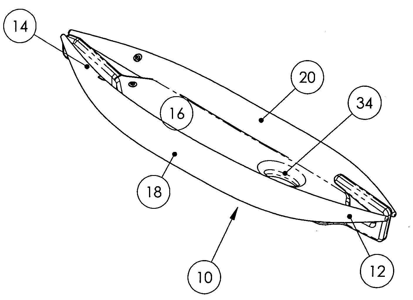
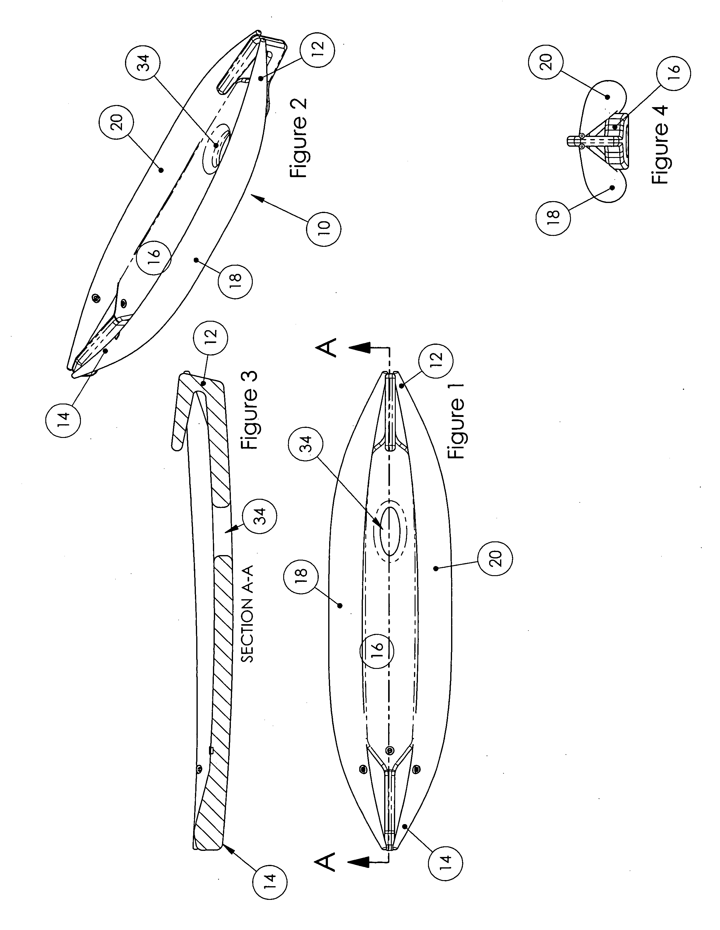
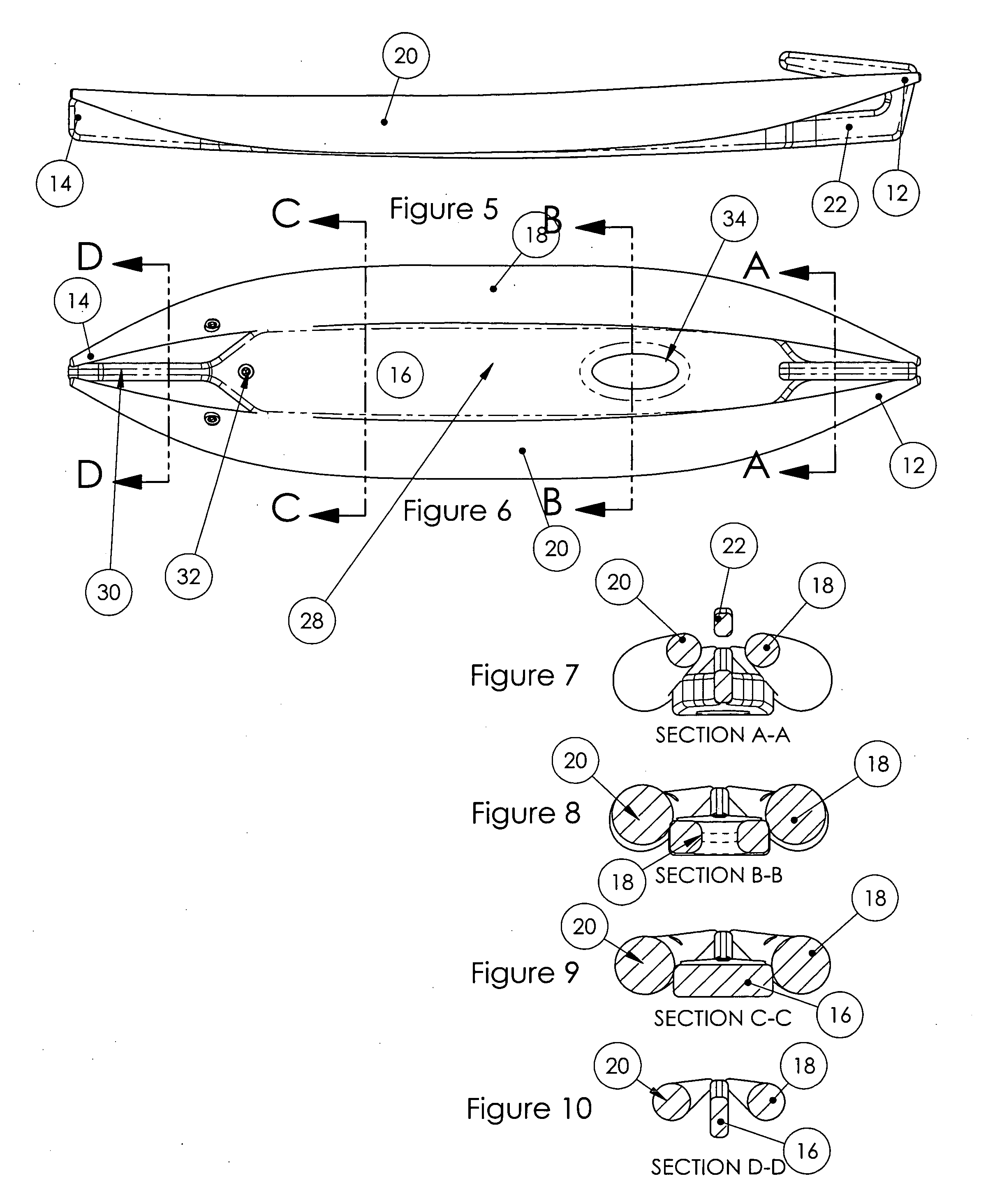
[0047]In one embodiment, the watercraft, generally 10, when inflated has a bow 12 and stem 14. The watercraft has three inflatable airtight chambers, an air chamber 16 forming the bottom or floor of the watercraft 10. The air chamber 16 extends generally from bow to stern. There are two inflatable side air chambers 18 and 20 which also extend generally from bow to stern.

[0048]At the bow, the bottom or floor air chamber 16 reduces to a narrow conduit 22 which turns up and back as shown in FIGS. 5, 7 and 22, forming, when inflated, the center of bow 12. The side air chambers 18 and 20 also narrow at the bow as shown in FIGS. 6 and 7.

[0049]At the stern 14, the bottom air chamber 16 and the side air chambers 18 and 20 also narrow at 19, as best shown in FIG. 22. All of the air chambers are enclosed in a flexible outer plastic cover layer which snugly conforms to the underlying structure.

[0050]The central or bottom air chamber 16 at its extrem...


PUM


Abstract

An air inflatable watercraft, preferably having a bow and stern, and having a cockpit, a bottom area forming part of said cockpit having a through opening therein adapted to receive a human operated propulsion mechanism which can be operated from the cockpit to propel the watercraft.An air inflatable watercraft having an inflatable, airtight bow and stern, and having a bottom area between two side inflatable, airtight compartments which run essentially the length of the watercraft, upon inflation the two side compartments at least partially extend above the bottom to provide a cockpit therebetween, and the inflated bow and stern form a configuration which is adapted to be efficiently propelled, viz., adapted to cut through the water. This embodiment can be hand rowed or provided with a pedaled propulsion mechanism provided a through opening is built into the bottom.An air inflatable watercraft having a bow and stern and having a central airtight compartment and two side airtight compartments running essentially the length of the watercraft, upon inflation the central compartment forms the bottom, stern and bow, and the two side compartments at least partially extend above the bottom to provide a cockpit therebetween. The central compartment has a through opening adapted to receive a human operated propulsion mechanism.

Description

[0001]The application claims the benefit of U.S. Provisional Application No. 60 / 962,999, filed Aug. 1, 2007, the disclosure of which is expressly incorporated herein by reference.FIELD OF INVENTION[0002]This invention relates to human propelled inflatable watercraft.BACKGROUND OF INVENTION[0003]Many types of inflatable watercraft are known. They range in size from small inner-tube type watercraft without propulsion to kayak-like watercraft and up to large inflatable boats with outboard engines to propel them.[0004]Kayaks including foot pedaled kayaks are known. Typically, pedalable kayaks are relatively long and made of a rigid plastic material. Consequently, for transport a pedalable kayaks must be towed from place to place on a trailer, or secured to a roof top carrier. Because they are rigid, considerable space is required for storage when the kayak is not in use and they are generally difficult to store in a garage, on a large boat or in a motor home due to it large size. With t...

Claims


Application Information

Patent Timeline
Patent Type & Authority Applications(United States)
IPC IPC(8): B63B7/08
CPCB63B35/71B63B7/08B63B34/22B63B34/23B63B34/26B63H2016/202
Inventor CZARNOWSKI, JAMES T.KETTERMAN, GREGORY S.KARDAS, JASON CHRISTOPHERDOW, PHILIP JAMES
Owner HOBIE CAT IP LLC
Learn More