Sterilizing Device With Ultraviolet Ray And Microwave Oven Having The Same

Inactive Publication Date: 2009-02-05
LG ELECTRONICS INC
View PDF5 Cites 29 Cited by
  • Summary
  • Abstract
  • Description
  • Claims
  • Application Information

AI Technical Summary

Benefits of technology

[0027]According to the present invention, there are advantages in that the microwave oven with various functi

Problems solved by technology

However, the UV sterilizer and the microwave oven configured as above according to the prior art have the following problems.
However, since both the articles and the UV lamp are stationary, there is a problem in that it is not easy to eff

Method used


Image

  • Sterilizing Device With Ultraviolet Ray And Microwave Oven Having The Same
  • Sterilizing Device With Ultraviolet Ray And Microwave Oven Having The Same
  • Sterilizing Device With Ultraviolet Ray And Microwave Oven Having The Same

Examples


Example

BEST MODE

[0034]Hereinafter, preferred embodiments of an ultraviolet sterilizer and a microwave oven including the same according to the present invention will be described in detail with reference to the accompanying drawings.
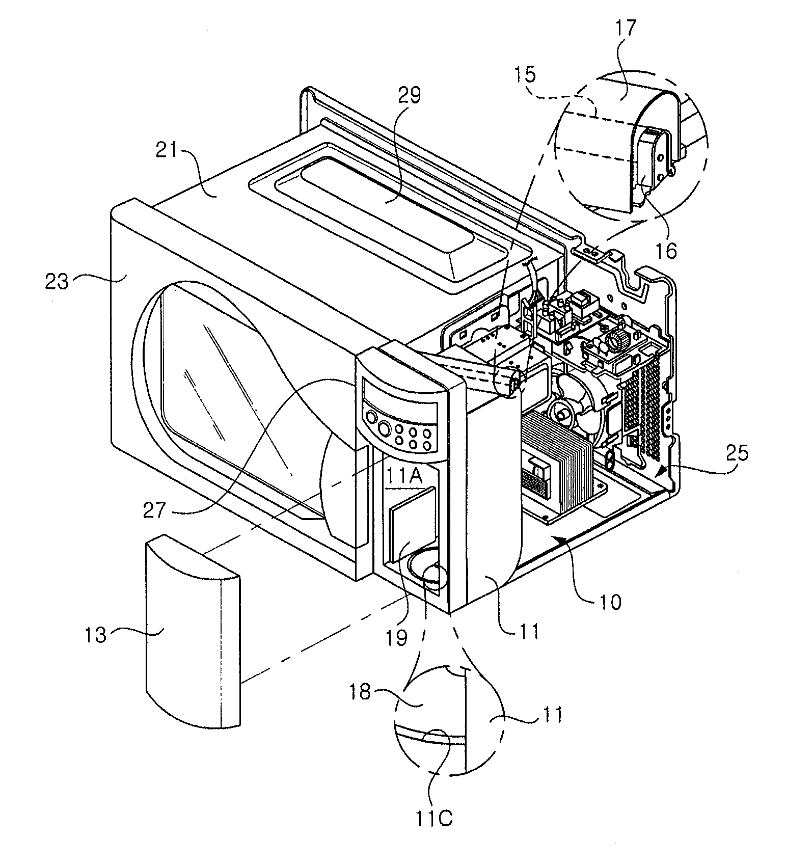
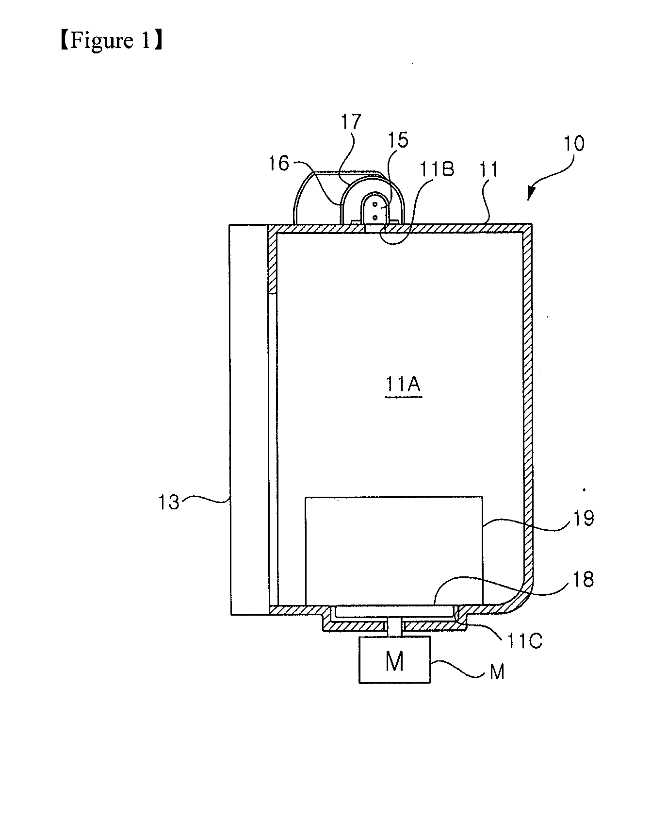
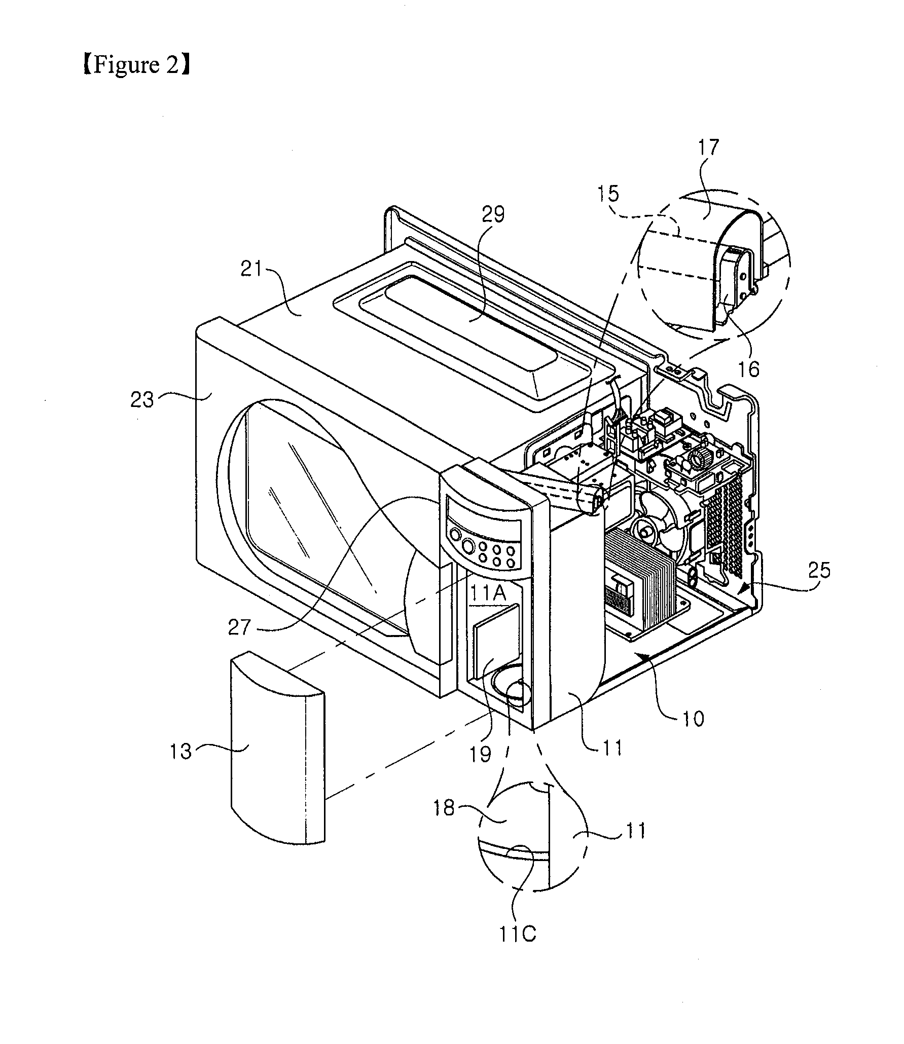
[0035]FIG. 1 is a side sectional view showing an ultraviolet (UV) sterilizer according to a preferred embodiment of the present invention, and FIG. 2 is a perspective view showing a microwave oven having the UV sterilizer according to the preferred embodiment of the present invention.

[0036]As shown in these figures, an external appearance of the UV sterilizer 10 is defined by a sterilizer casing 11. The sterilizer casing 11 takes the shape of a hexahedron with an open front side. In addition, a sterilizing chamber 11A is provided in the sterilizer casing 11. Articles can be sterilized in the sterilizing chamber 11A, and a front side of the sterilizing chamber is open toward the outside such that articles to be sterilized can be taken in and out of the chamber t...


PUM


Abstract

The present invention relates to an ultraviolet (UV) sterilizer and a microwave oven including the same. The ultraviolet sterilizer of the present invention comprises a sterilizer casing having an open side and defining a sterilizing chamber, a sterilizer door installed at one side of the sterilizer casing to selectively open or close the sterilizing chamber, a UV lamp installed at another side of the sterilizer casing to irradiate UV rays into the sterilizing chamber, and a turntable rotatably installed on a floor of the sterilizing chamber to place an article to be sterilized onto a top surface thereof. According to the present invention, there are advantages in that the microwave oven with various functions can be provided and articles to be sterilized can be more efficiently sterilized using the microwave oven.

Description

TECHNICAL FIELD[0001]The present invention relates to a microwave oven, and more particularly, to an ultraviolet (UV) sterilizer for sterilizing articles using ultraviolet rays and a microwave oven including the same.BACKGROUND ART[0002]FIG. 5 is a perspective view showing a conventional UV sterilizer.[0003]As shown in this figure, a sterilizing chamber 83 for sterilizing articles thereon is provided in a main body 81 of the sterilizer. The sterilizing chamber 83 is selectively opened or closed by means of a sterilizer door 85 installed pivotally to one end on a front side of the main body 81 in a front and rear direction of the main body 81.[0004]In addition, at least one UV lamp (not shown) is provided on the ceiling of the sterilizing chamber 83. The UV lamp emits UV rays to the sterilizing chamber 83 so as to sterilize articles provided in the sterilizing chamber. Further, a control unit 87 for receiving various signals used to operate the UV sterilizer and displaying a variety ...

Claims


Application Information

Patent Timeline
IPC IPC(8): F24C7/02A61L2/10
CPCA23L3/28A61L2/10H05B2206/045H05B6/6426A61L2/12
Inventor LEE, WANG-LIMHWANG, HYUN-CHULCHOI, SUNG-HO
Owner LG ELECTRONICS INC
Why Eureka
Try Eureka