Vehicle source device

a vehicle source and capacitor technology, applied in the direction of capacitor propulsion, battery/fuel cell control arrangement, safety/protection circuit, etc., can solve the problems of difficult application of capacitor heating method, capacitor temperature inside of the capacitor is accurate, and the vehicle source device cannot meet the specification of the original vehicle source devi

Inactive Publication Date: 2009-02-05
PANASONIC CORP
View PDF0 Cites 71 Cited by
  • Summary
  • Abstract
  • Description
  • Claims
  • Application Information

AI Technical Summary

Benefits of technology

[0024]According to the present configuration, an accurate temperature of the inside of the capacitor can be obtained. As a result, the temperature can be accurately raised up to the target temperature by taking the ability of the capacitor into consideration according to the vehicle source device of the present invention, and thus a vehicle source device capable of sufficiently exhibiting the original required performance is obtained even if the hybrid vehicle is activated at low temperature.

Problems solved by technology

Generally, a battery is used as a power supply to electrically perform hydraulic control of a vehicle, but in this case, hydraulic control cannot be performed with only the battery if power supply is interrupted for some reason, and braking of the vehicle might become impossible.
The capacitor of such vehicle source device cannot satisfy the specification for the original vehicle source device due to the characteristic of the general capacitor that the internal resistance suddenly becomes large and the capacity suddenly becomes small at low temperature, in particular, when the vehicle is activated while being stored under low temperature.
According to such operation, the temperature of battery 9 serving as a storage element can be reliably raised, but it is difficult to apply such method to the capacitor.
Regarding such aspect, the method is inaccurate in terms of temperature-rise control to the target temperature in time of change in capacitor ability since correction with respect to degradation is not taken into consideration in the conventional method.

Method used


Image

  • Vehicle source device
  • Vehicle source device
  • Vehicle source device

Examples


first embodiment

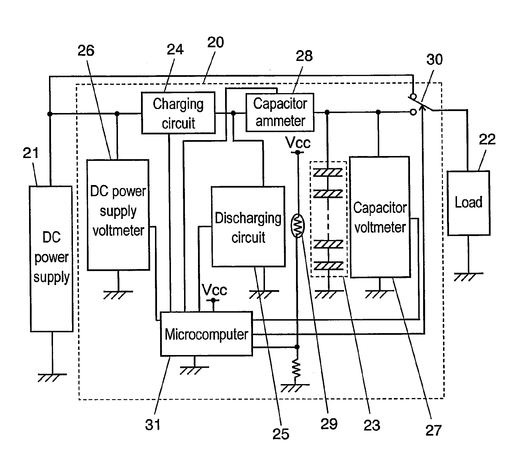
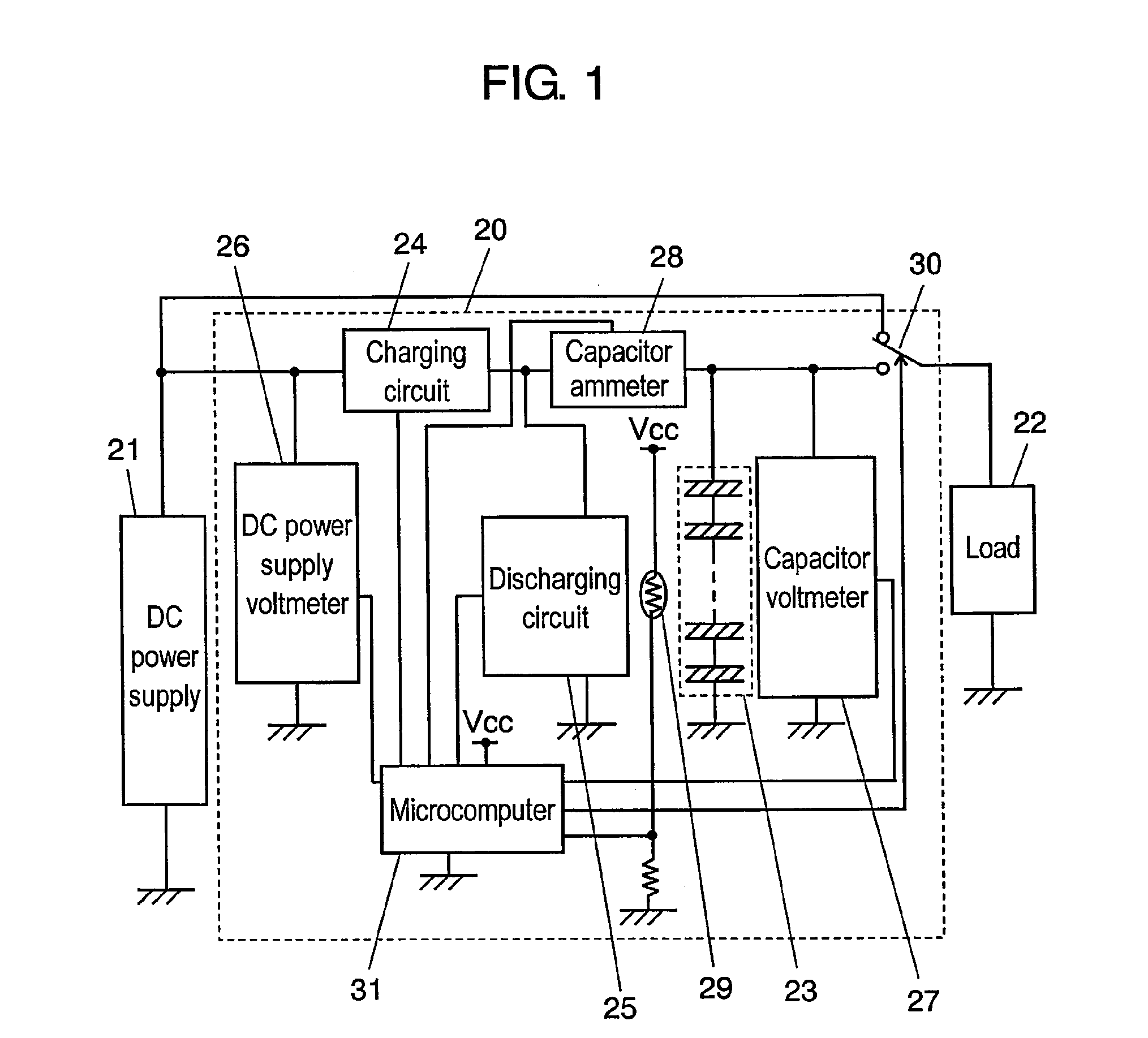
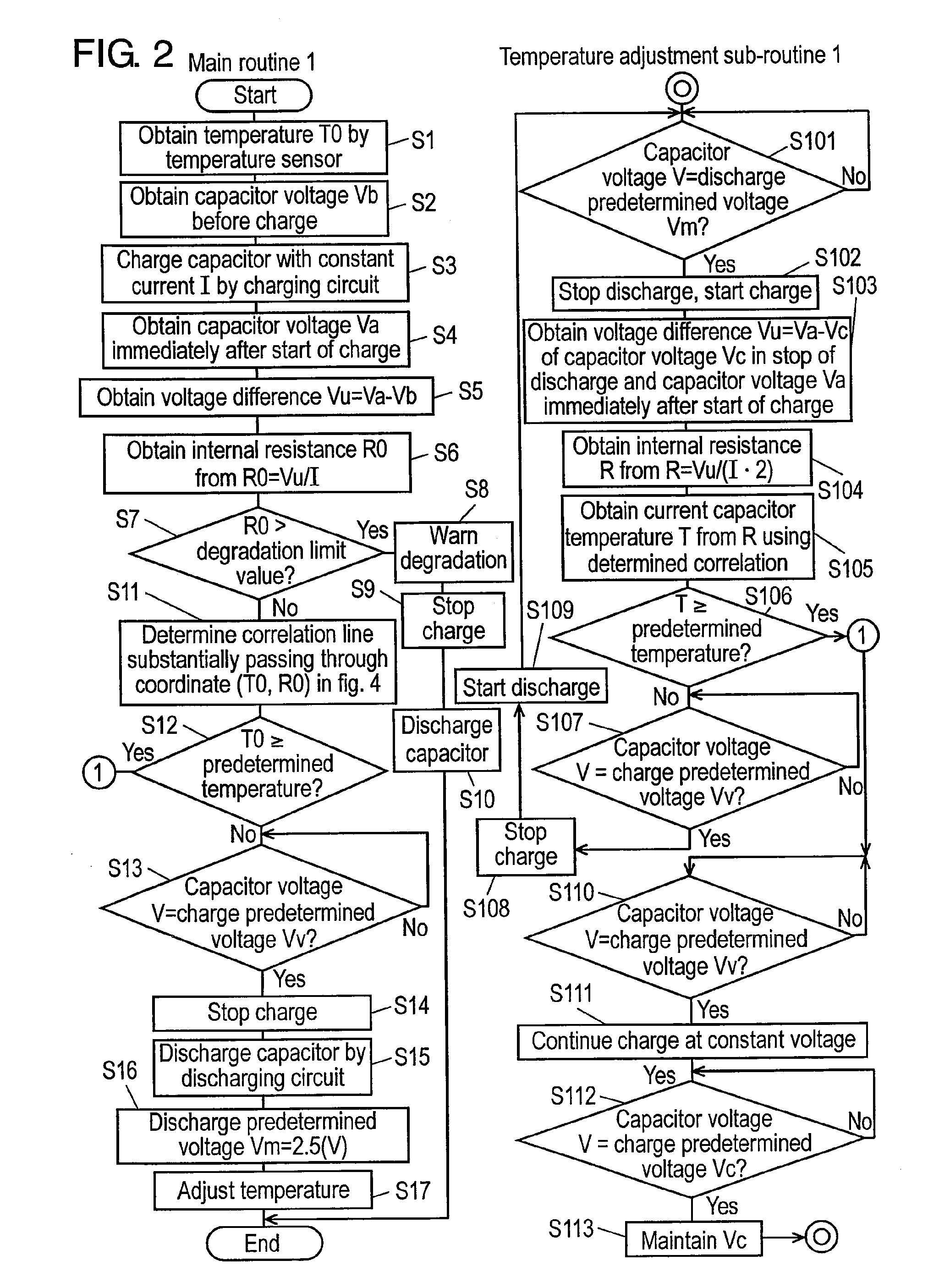
[0055]FIG. 1 is a block circuit diagram of vehicle source device 20 according to a first embodiment of the present invention. FIG. 2 is a flowchart showing an operation of vehicle source device 20 in the first embodiment of the present invention. FIG. 3A is a temporal capacitor voltage characteristics diagram and FIG. 3B is a charging / discharging current characteristics diagram in time of temperature-rise of vehicle source device 20 in the first embodiment of the present invention. FIG. 4 is a temperature characteristics diagram of an internal resistance and a capacity corresponding to degradation of the capacitor of the vehicle source device in the first embodiment of the present invention.

[0056]In FIG. 1, vehicle source device 20 is connected between direct current (DC) power supply 21 including a battery and load 22 for performing vehicle braking control.

[0057]Detailed configuration of vehicle source device 20 is as follows.

[0058]First, capacitor 23 for charging the power of DC p...

second embodiment

[0170]FIG. 5 is a flowchart showing the operation of vehicle source device 20 according to a second embodiment of the present invention. FIG. 6A is a temporal capacitor voltage characteristics diagram and FIG. 6B is a charging / discharging current characteristics diagram in time of temperature-rise of vehicle source device according to the second embodiment of the present invention.

[0171]The configuration of the second embodiment is substantially the same as the configuration of the first embodiment, and thus description will be made with reference to FIG. 1 and detailed description of the same portions will be omitted.

[0172]Difference lies in that discharging circuit 25 has a configuration in which a discharge switch (not shown) that is turned ON / OFF by a signal of microcomputer 31 and a load resistor (not shown) are connected in series.

[0173]Therefore, when discharging the charges of capacitor 23, the discharge switch arranged in discharging circuit 25 is turned ON to flow the curr...

third embodiment

[0209]FIG. 7 is a flowchart showing the operation of vehicle source device 20 according to a third embodiment of the present invention. FIG. 8A is a temporal partial capacitor voltage characteristics diagram and FIG. 8B is a temporal partial charging / discharging current characteristics diagram in time of temperature-rise of vehicle source device according to the third embodiment of the present invention.

[0210]The configuration of the third embodiment is substantially the same as the configuration of the first embodiment, and thus description will be made with reference to FIG. 1 and detailed description of the same portions will be omitted. Similar to the first embodiment, discharging circuit 25 is also a constant current discharging circuit.

[0211]In FIG. 7, same reference numerals as in FIG. 2 are used for the operating portion same as the first embodiment and the description will be omitted.

[0212]The characteristic portions of the third embodiment lie in that the operation after S...


PUM


Abstract

A vehicle source device capable of performing a more accurate temperature-rise corresponding to the ability of the capacitor is provided. The correlation of the temperature and the internal resistance corresponding to the ability of the current capacitor in time of activation is obtained in advance, the internal resistance is obtained for every repetition of charge / discharge, and the temperature of the inside of the capacitor is obtained from the correlation. Since the accurate temperature of the inside of the capacitor is obtained, the capacitor is accurately temperature-raised to the target temperature.

Description

TECHNICAL FIELD[0001]The present invention relates to an emergency power supply of electronic equipment that uses battery etc., in particular, to a vehicle source device used in an electronic brake system etc. for electrically braking a vehicle.BACKGROUND ART[0002]Development in hybrid cars and electric automobiles is rapidly advancing in recent years, and accompanied therewith, various proposals from a mechanical hydraulic control to an electrical hydraulic control of a conventional art have been proposed regarding the braking of the vehicle.[0003]Generally, a battery is used as a power supply to electrically perform hydraulic control of a vehicle, but in this case, hydraulic control cannot be performed with only the battery if power supply is interrupted for some reason, and braking of the vehicle might become impossible.[0004]Thus, a proposal is made to respond to an emergency by mounting a storage element such as a large-capacity capacitor as an emergency auxiliary power supply ...

Claims


Application Information

Patent Timeline
Patent Type & Authority Applications(United States)
IPC IPC(8): H02J7/00B60W10/26
CPCB60L11/005H02J7/0029H02J7/1415H02J7/1453H02J7/345Y02T10/705B60L1/003B60L11/1872B60L2240/545B60L2260/42Y02T10/7005Y02T10/7022B60L50/40B60L58/25H02J7/007194Y02T10/70
Inventor ODAJIMA, YOSHIMITUMORITA, KAZUKI
Owner PANASONIC CORP
Why Eureka
Try Eureka