Head drive apparatus of ink jet printer, head driving method, and ink jet printer

Active Publication Date: 2009-02-05
SEIKO EPSON CORP
View PDF75 Cites 26 Cited by
  • Summary
  • Abstract
  • Description
  • Claims
  • Application Information

AI Technical Summary

Benefits of technology

[0016]A method for driving a head of an ink jet printer and a head drive apparatus according to the above aspects, in which the method for outputting a modulated signal which is pulse modulated based on modulated signal data stored in a storage unit such as a memory, amplifying the modulated signal using a digital power amplifier, and smoothing the amplified digital signal to output the signal to the actuators as a drive pulse, thereby a modulated signal is efficiently power-amplified by a digital power amplifier having a high amplification efficiency, which eliminates a cooling unit such as a cooling plate radiator and enables a mount of a drive pulses output circuit to an ink

Problems solved by technology

However, the conventional ink jet printer in which transistors connected in push-pull connection amplifies the current of an actuator drive pulse has a

Method used


Image

  • Head drive apparatus of ink jet printer, head driving method, and ink jet printer
  • Head drive apparatus of ink jet printer, head driving method, and ink jet printer
  • Head drive apparatus of ink jet printer, head driving method, and ink jet printer

Examples


Embodiment Construction

[0045]A first embodiment of an ink jet printer according to the present invention will be described with reference to the drawings.

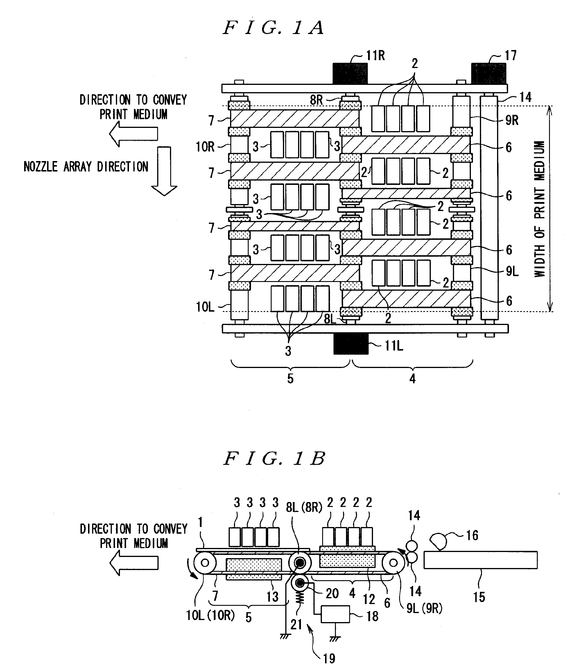
[0046]FIGS. 1A and 1B are the overall configuration diagrams of an ink jet printer according to this embodiment: FIG. 1A is a top plain view of the printer; and FIG. 1B is a front view of the printer. In FIGS. 1A and 1B, a print medium 1 is a line head ink jet printer that is conveyed in a direction from the right to the left indicated by the arrow in the figure and printed in a printing area on the way of the conveyor. However, the ink jet head according to the present embodiment is not arranged only at one place, but two ink jet heads are arranged at two places.

[0047]Reference numeral 2 in the figure denotes a first ink jet head being provided on the upstream side of the direction in which the print medium 1 is conveyed, and reference numeral 3 denotes a second ink jet head being provided on the downstream side of the direction. A first conveyor unit 4...


PUM


Abstract

With an appropriate signal transmission form, a drive pulse output circuit is mounted to an ink jet head, so that waveform distortion of an actuator drive pulse for jet of ink drops is inhibited or prevented. Modulated signal data in memory is read to output a modulated signal, which is power-amplified by a digital power amplifier. The amplified digital signal is smoothed to be output to an actuator as a drive pulse. As a result, the digital power amplifier having high amplification efficiency efficiently amplifies the power of the modulated signal, thereby eliminating the need to use a cooling unit. The drive pulse output circuit can be mounted to the ink jet heads, thereby shortening the transmission path of an actuator drive pulse, which inhibits or prevents any waveform distortion of the drive pulse. The transmission of the modulated signal data DATA is implemented with a low frequency.

Description

BACKGROUND[0001]1. Technical Field[0002]The present invention relates to a head drive apparatus of an ink jet printer in which a plurality of nozzles jet minute ink drops of liquid ink of a plurality of colors and particles of the ink (ink dots) are formed on a print medium to draw pre-determined characters and images, and a head driving method.[0003]2. Related Art[0004]An ink jet printer as in the above generally accomplishes low-cost and high-quality color printed material easily. As such, it is widely used not only in offices but also by general users along with popularization of a personal computer and a digital camera.[0005]Generally, in such an ink jet printer, a moving part called a carriage, for example, integrally comprising ink cartridges and print heads (also called as ink jet heads) moves back and forth on a print medium in a direction crossing a direction to convey the medium, and nozzles of the print head jet (eject) liquid ink drops to form minute ink dots on the prin...

Claims


Application Information

Patent Timeline
IPC IPC(8): B41J29/38
CPCB41J2/04541B41J2/04588B41J2/04581B41J2/04593B41J2/04596
Inventor SUZUKI, TOSHIYUKITABATA, KUNIOSHINKAWA, OSAMUHATANO, TOMOKIOSHIMA, ATSUSHI
Owner SEIKO EPSON CORP
Why Eureka
Try Eureka