Centrifugal compressor, impeller and operating method of the same

a centrifugal compressor and impeller technology, applied in the direction of machines/engines, stators, liquid fuel engines, etc., can solve the problems of difficult to determine whether the operating range could be increased or not, and the relationship between the appropriate operating range and the blade angle distribution is difficult to find, so as to achieve the effect of widening the operating rang

Active Publication Date: 2009-02-05
HITACHI IND PROD LTD
View PDF7 Cites 37 Cited by
  • Summary
  • Abstract
  • Description
  • Claims
  • Application Information

AI Technical Summary

Benefits of technology

[0012]According to the above configuration, it is possible to change the area of the flow channel and accelerate and decelerate the working fluid by giving a predetermined blade angle distribution to the geometry of the blade (shroud side and hub side) of the impeller of the centrifugal compressor.
[0013]According to the centrifugal compressor having the above configuration, it is possible to provide a centrifugal compressor equipped with an impeller having a blade angle distribution that makes it possible to achieve a relatively wide operating range to solve the problems.

Problems solved by technology

Recently, it has been required to enlarge the operating range for a stable operation of the impeller, due to the increased concerns in the lifecycle cost, and problems relating to energy and the environment.
However, in this determination, it was difficult to find relationship between an appropriate operating range and the blade angle distribution.
Accordingly, it was difficult to determine whether the operating range could be increased or not by adjusting the blade angle distribution.
As described above, since it is difficult to determine the blade angle distribution on the basis of the relation with the operating range, when the operating range for the target specifications in insufficient, the insufficiency of the operating range is compensated and the operating range is enlarged by adjusting the main dimensions, such as longitudinal length and diameter of the inlet of the impeller, or by applying casing treatment for increasing the operating range of the small flow rate side.
Accordingly, examination items were increased, which reduced the efficiency in the design.
Further, since additional process of applying the casing treatment was required to increase the operating range for the small flow rate side, manufacturing cost is increased and efficiency of performance is correspondingly decreased.

Method used


Image

  • Centrifugal compressor, impeller and operating method of the same
  • Centrifugal compressor, impeller and operating method of the same
  • Centrifugal compressor, impeller and operating method of the same

Examples


first embodiment

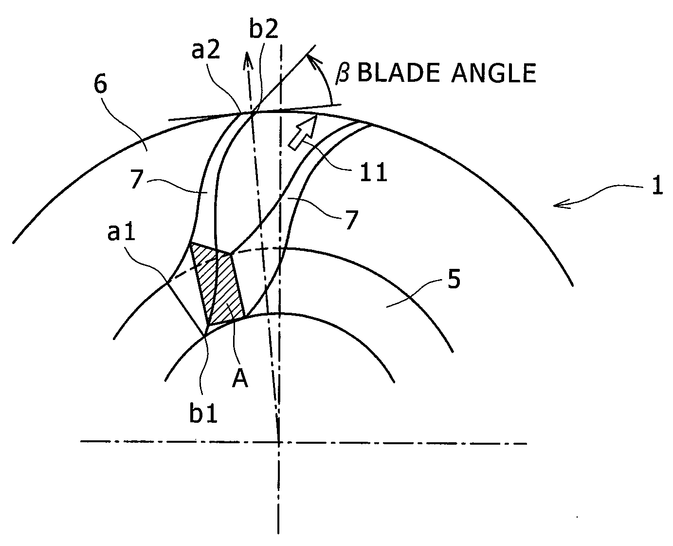
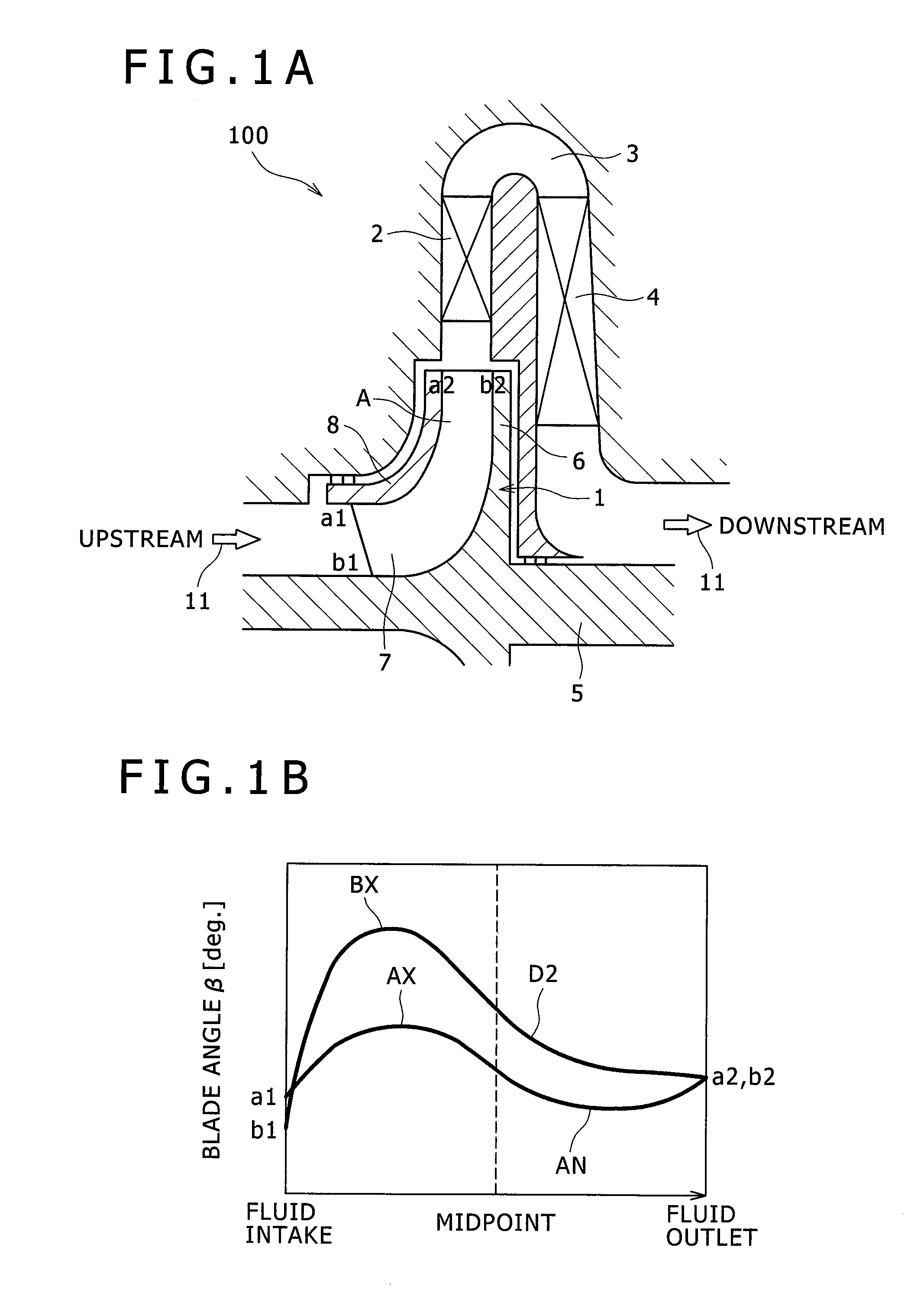
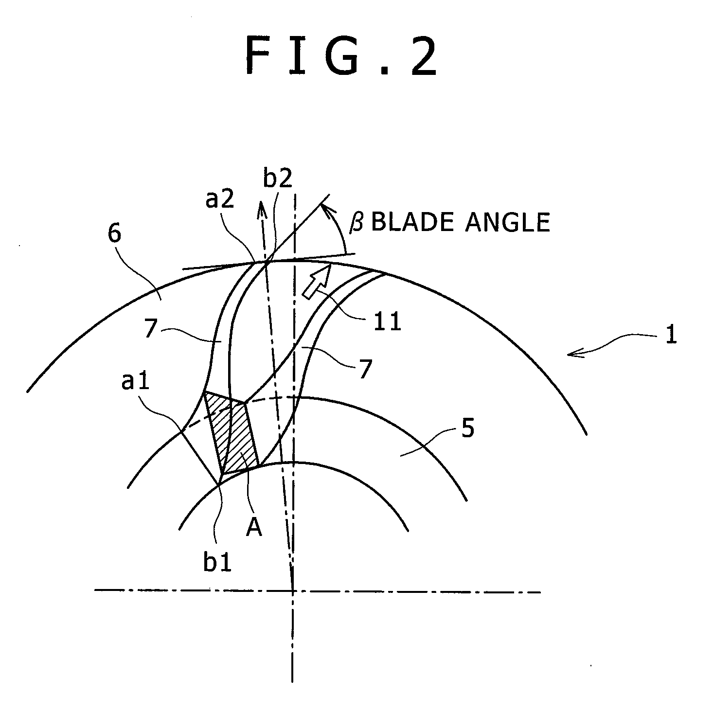
[0027]A first embodiment of the invention is described hereafter in detail with reference to the accompanying drawings. FIG. 1A is a cross-sectional view illustrating the configuration of a centrifugal compressor according to this embodiment. FIG. 1B is a view illustrating a blade angle distribution attached to the impeller shown in FIG. 1A. FIG. 2 is a view illustrating the definition of the blade angle distribution for each portion of the blade of the impeller.

[0028]As shown in FIG. 1A, the centrifugal compressor 100 according to the first embodiment includes an impeller 1, a diffuser 2, a return channel 3, and a return vane 4, which are sequentially disposed from the upstream (the left side of FIG. 1A) to the downstream.

[0029]The components and operation according to flow of working fluid 11 are described below.

[0030]The working fluid 11 is sucked into the centrifugal compressor 100 by the rotation of the impeller 1 and passes through a flow channel A formed between plural blades...

second embodiment

[0047]Next, a second embodiment of a centrifugal compressor according to the invention is described hereafter. The same components as the first embodiment (see FIG. 1) are not described in a centrifugal compressor 101 according to this embodiment and other components different from the first embodiment are described in priority. FIG. 5A is a diagram illustrating a rake angle that is made by a straight line connecting the blade front end a2 of a fluid outlet a2 to b2 with the hub side b2 and the circumference of the circular plate 6 that is perpendicular to the center of the rotary shaft 5. FIG. 5B shows the blade of the outlet seen from the fluid outlet a2 to b2 to the rotary shaft 5 and the rake angle is the angle θ of the blade.

[0048]A blade angle distribution of an impeller according to this embodiment is described. In this embodiment, as in the first embodiment, the outline of the front side a1 to a2 (shroud side) of the blade 7 from the upstream to the downstream of the blade 7...

third embodiment

[0051]Next, a third embodiment of a centrifugal compressor according to the invention is described. In a centrifugal compressor 102 according to this embodiment, the same components as the first embodiment (see FIG. 1) or the second embodiment are not described and other components different from the first embodiment are described in priority. FIG. 6 shows a vertical cross-section of this embodiment.

[0052]A blade angle distribution of an impeller according to this embodiment is described. In this embodiment, as in the first embodiment, the outline of the front side a1 to a2 (shroud side) of the blade 7 from the inlet to the outlet of the working fluid 11 has a convex curve-shaped blade angle distribution where the first angle D1 has a local maximum point between a midpoint and the upstream, and has a concave curve-shaped blade angle distribution where the first angle D1 has a local minimum point between the midpoint and the downstream. Further, the outline of the hub side b1 to b2 o...


PUM


Abstract

A centrifugal compressor is equipped with an impeller having a blade angle distribution that makes it possible to achieve a relatively wide operating range. The blade angle of a shroud side facing a circular plate of a blade is termed a first angle and a blade angle of a hub side disposed at the circular plate is a second angle. The shroud side is formed in a curved shape having an angle distribution from a front area in a shaft direction toward a centrifugal direction in which the first angle is the local maximum point before a substantially middle portion and the local minimum point after the substantially middle point. The hub side is formed in a curved shape having an angle distribution from the front area in the shaft direction toward the centrifugal direction in which the second angle is the maximum local point before the substantially middle portion.

Description

BACKGROUND OF THE INVENTION[0001]1. Field of the Invention[0002]The present invention relates to a centrifugal compressor, and an impeller and an operating method of the same, particularly blade geometry of the impeller.[0003]2. Description of the Related Art[0004]A centrifugal compressor that compresses fluid using a rotary impeller has been widely used in a variety of plants in the related art. Recently, it has been required to enlarge the operating range for a stable operation of the impeller, due to the increased concerns in the lifecycle cost, and problems relating to energy and the environment.[0005]The operating range for a stable operation of the impeller is determined by a surge that makes periodic change in pressure or flow rate due to increase of a recirculation area that is generated by flow separation when flow rate decreases more at a small flow rate side, and choke that does not increase any more at a large flow rate side.[0006]The blade geometry of the impeller of th...

Claims


Application Information

Patent Timeline
Patent Type & Authority Applications(United States)
IPC IPC(8): F04D27/00F01D5/04F01D5/14
CPCF04D29/30F04D29/284
Inventor YAGI, MANABUKISHIBE, TADAHARUSHIBATA, TAKANORINISHIDA, HIDEOKOBAYASHI, HIROMIKUWANO, TETSUYA
Owner HITACHI IND PROD LTD
Why Eureka
Try Eureka