Method and apparatus for spinal facet fusion

a facet fusion and facet technology, applied in the field of surgical methods and equipment, can solve the problems of unstable affected spinal segments, substantial pain for patients, and worsening pain for patients, and achieve the effect of facilitating fusion

Active Publication Date: 2009-02-05
VG INNOVATIONS
View PDF100 Cites 167 Cited by
  • Summary
  • Abstract
  • Description
  • Claims
  • Application Information

AI Technical Summary

Problems solved by technology

Disc herniation is a condition where a spinal disc bulges from between two vertebral bodies and impinges on adjacent nerves, thereby causing pain.
In some cases, the spinal fixation leaves the affected spinal segment unstable.
The misengagement of the spinal facets can cause substantial pain to the patient.
Furthermore, when left untreated, such misengagement of the spinal facets can result in the degeneration of the cartilage located between opposing facet surfaces, ultimately resulting in osteoarthritis, which can in turn lead to worsening pain for the patient.
However, the clinical success of this approach was limited.
This is believed to be because the Stein approach did not adequately restrict facet motion.
In particular, it is believed that movement of Stein's conical plug within its hole permitted unwanted facet movement to occur, thereby undermining facet fusion.
Furthermore, the Stein approach also suffered from plug failure and plug migration.

Method used


Image

  • Method and apparatus for spinal facet fusion
  • Method and apparatus for spinal facet fusion
  • Method and apparatus for spinal facet fusion

Examples


Embodiment Construction

In General

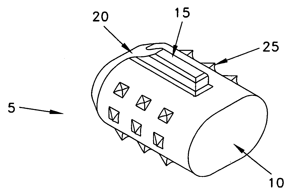
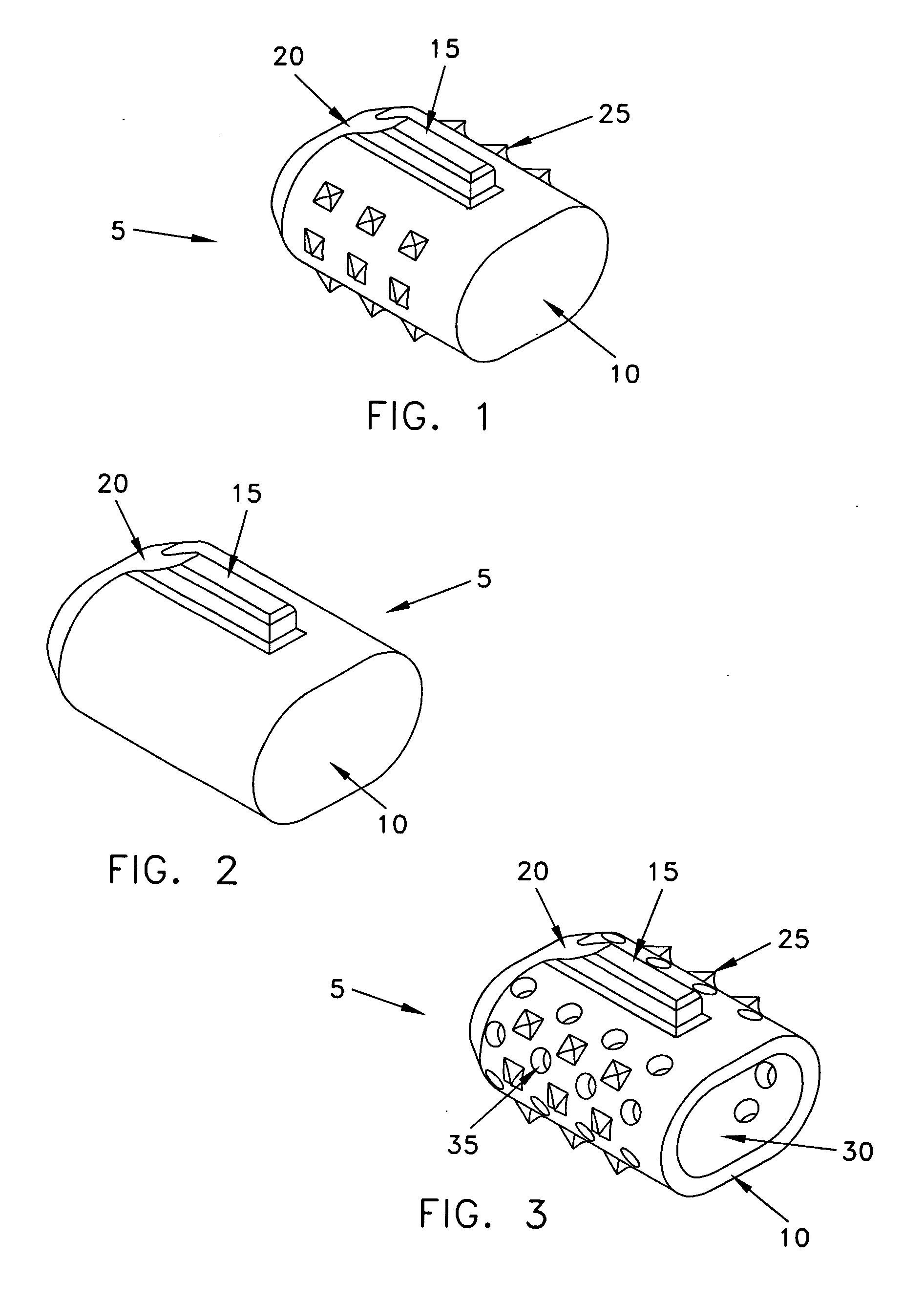
[0054]Looking first at FIG. 1, there is shown a novel spinal facet fusion implant 5 formed in accordance with the present invention. Fusion implant 5 generally comprises a body 10 and at least one stabilizer 15.

[0055]Body 10 comprises an elongated element having structural integrity. Preferably the distal end of body 10 (and the distal end of stabilizer 15 as well) is chamfered as shown at 20 to facilitate insertion of fusion implant 5 into the facet joint, as will hereinafter be discussed. Preferably, and as seen in FIG. 1, body 10 has a rounded rectangular cross-section, or an ovoid cross-section, a laterally-extended cross-section, or some other non-round cross-section, so as to inhibit rotation of body 10 about a longitudinal center axis. If desired, body 10 may include a plurality of barbs (i.e., forward biting teeth) 25 extending outwardly therefrom. Barbs 25 are designed to permit body 10 to be inserted into the facet joint and to impede retraction of body 10 out of...


PUM


Abstract

A spinal facet fusion implant comprising:an elongated body having a distal end, a proximal end and a longitudinal axis extending between the distal end and the proximal end, the elongated body having a cross-sectional profile characterized by a primary axis and a secondary axis; andat least one stabilizer extending radially outwardly from the elongated body in the secondary axis;wherein the elongated body has a length along the primary axis which is less than the combined width of the spinal facets making up a facet joint;and further wherein the at least one stabilizer has a width which is sized to make a press fit into the gap between the spinal facets making up a facet joint.

Description

REFERENCE TO PENDING PRIOR PATENT APPLICATION[0001]This patent application claims benefit of pending prior U.S. Provisional Patent Application Ser. No. 60 / 939,615, filed May 22, 2007 by Tov Vestgaarden for PERCUTANEOUS SPINAL FACET FIXATION DEVICE FOR FACET FUSION (Attorney's Docket No. VG-1 PROV), which patent application is hereby incorporated herein by reference.FIELD OF THE INVENTION[0002]This invention relates to surgical methods and apparatus in general, and more particularly to surgical methods and apparatus for fusing spinal facets.BACKGROUND OF THE INVENTION[0003]Disc herniation is a condition where a spinal disc bulges from between two vertebral bodies and impinges on adjacent nerves, thereby causing pain. The current standard of care for surgically treating disc herniation in patients who have chronic pain and who have (or are likely to develop) associated spinal instability is spinal fixation. Spinal fixation procedures are intended to relieve the impingement on the nerv...

Claims


Application Information

Patent Timeline
Patent Type & Authority Applications(United States)
IPC IPC(8): A61B17/70A61F2/44A61B19/00
CPCA61B17/7064A61F2002/30622A61F2/4405
Inventor VESTGAARDEN, TOV
Owner VG INNOVATIONS
Why Eureka
Try Eureka