
Lopper

Inactive Publication Date: 2009-02-12
ARCAS CORP
View PDF10 Cites 25 Cited by
  • Summary
  • Abstract
  • Description
  • Claims
  • Application Information

AI Technical Summary

Benefits of technology

[0006]The present invention has been accomplished under these circumstances in view. It is one objective of the present invention to provide a lopper that facilitates effort-saving pruning and has a rod with a length, which is adjustable according to the altitude of the branches and leaves to be pruned.
[0008]The disclosed lopper has the advantages of effort-saving operation, simplified construction, light weight, easy gripping, easy controlling, and adjustable operational angle of the shear assembly. Additionally, the lopper of the present invention allows a user to adjust the extending length of the handling rod according to the altitude of the branches and leaves to be pruned.

Problems solved by technology

However, as the conventional lopper has the complexly structured and bulky shears mounted on the top of the rod, it would be difficult for a user to maintain the balance of the lopper while holding and operating the same.
Besides, the heavy weight of the shears of the conventional lopper substantially burdens the user.
Moreover, the intricate linkages and ropes settled around the shears are liable to get tangled with luxuriant branches and leaves where a user tries to stretch the shears through, therefore resulting in retarded efficiency of pruning.
Nevertheless, linkage efficiency is not perfectly performed in '315 Patent because the distance between the point where the chain exerts a force on the blade and the pivot point is not long enough for facilitating effort-saving pruning.
Furthermore, as the rod of the '315 lopper has a fixed length which is not extendable, if a user wants to prune branches and leaves at a relatively higher location, a ladder has to be implemented to lift the user and this may disadvantageously render inconvenience and danger to the user.

Method used


Image

  • Lopper
  • Lopper
  • Lopper

Examples


Embodiment Construction

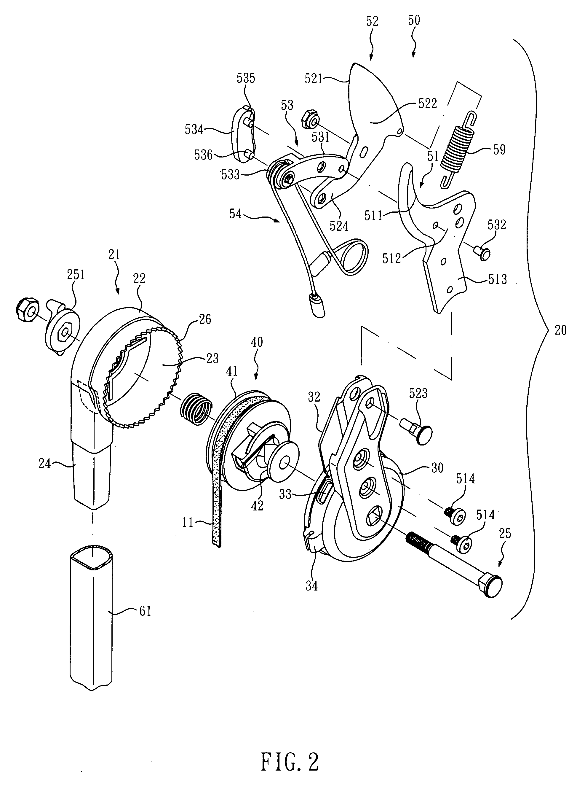
[0034]As shown in FIG. 1, the lopper of the present invention primarily comprises a slender rod 10 and a pruning mechanism 20 mounted on a top of the slender rod 10. The slender rod 10 includes an apparently visible outer tube 60, an inner tube 61 shiftably telescoped inside the outer tube 60, an extension-control unit 65 provided at a border region between the outer and inner tubes 60, 61, a first actuating unit 70 deposited at the outer tube 60 and a second actuating unit 80 deposited at a bottom of the outer tube 60.

[0035]The pruning mechanism 20, referring toFIGS. 1 through 5, comprises three parts, which are a drum 21, an axial wheel 40 and a shear assembly 50, wherein the drum 21 is constructed form combining a fixed portion 22 and a rotatable portion 30 face to face.

[0036]The fixed portion 22 is substantially shaped as a round box for providing a round space 23 therein. A combining portion 24 radially extends outward from the fixed portion 22 for being inserted into a top of ...


PUM


Abstract

A lopper comprises a slender rod and a pruning means mounted on a top of the rod. The slender rod is composed of an inner tube and an outer tube telescoped mutually such that the inner tube is shiftable in the outer tube for changing the length it jutting out from the outer tube. An extension-control unit is provided at the border region between the inner tube and the outer tube for positioning the inner tube. A first actuating unit and a second actuating unit are provided at the outer surface of the outer tube. The first and second actuating units are connected with the pruning means through a first rope, a second rope and a third rope so that when a user pulls the first or second actuating unit, a shear assembly of the pruning means can be closed to cut branches and leaves of plants.

Description

BACKGROUND OF THE INVENTION[0001]1. Technical Field[0002]The present invention relates to gardening tools, and more particularly, to a lopper for pruning tree branches and leaves lying high.[0003]2. Description of Related Art[0004]A lopper is typically implemented to prune tree branches and leaves lying high, which is composed of a slender rod and a pair of shears mounted on the top of the rod. One general objective of loppers is to facilitate effort-saving operation. To achieve this objective, various mechanisms employing linkages and levers are applied to loppers, such as those disclosed in U.S. Pat. No. 6,178,644 and U.S. Pat. No. 4,649,646. However, as the conventional lopper has the complexly structured and bulky shears mounted on the top of the rod, it would be difficult for a user to maintain the balance of the lopper while holding and operating the same. Besides, the heavy weight of the shears of the conventional lopper substantially burdens the user. Moreover, the intricate...

Claims


Application Information

Patent Timeline
IPC IPC(8): B26B13/00
CPCA01G3/0255
Inventor SHAN, SU-HUA
Owner ARCAS CORP
Learn More