Grating with a plate detachably mounted in a frame for covering a drainage channel

a technology of drainage channel and plate, which is applied in the field of covering, can solve the problems of inability to interchange different “designs”, high construction cost in the case of larger model range, and inability to meet the requirements of construction, and achieve the effect of simplifying assembly

Inactive Publication Date: 2009-02-12
ACO SEVERIN AHLMANN GMBH & CO KG
View PDF4 Cites 3 Cited by
  • Summary
  • Abstract
  • Description
  • Claims
  • Application Information

AI Technical Summary

Benefits of technology

[0013]Additionally, the frame is preferably configured so that surface water drains into the drainage channel between the frame and the upper edges of the drainage channel. As a result, it is also possible to use completely closed surface elements and nevertheless to maintain a drainage function. On the other hand such “additional” drainage apertures do not cause trouble, if a usual grating is employed as surface element. In addition or as an alternative to such a drainage aperture between frame and upper edge of the channels it is possible to provide drainag...

Problems solved by technology

Since the various covers require different design principles for the fixing devices, hence for example steel gratings cannot be provided with the identical fixing devices as for cast iro...

Method used


Image

  • Grating with a plate detachably mounted in a frame for covering a drainage channel
  • Grating with a plate detachably mounted in a frame for covering a drainage channel
  • Grating with a plate detachably mounted in a frame for covering a drainage channel

Examples


Embodiment Construction

[0025]In the following description the same reference symbols are used for parts which are the same or have the same functions.

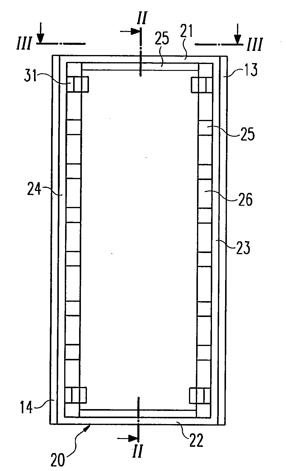
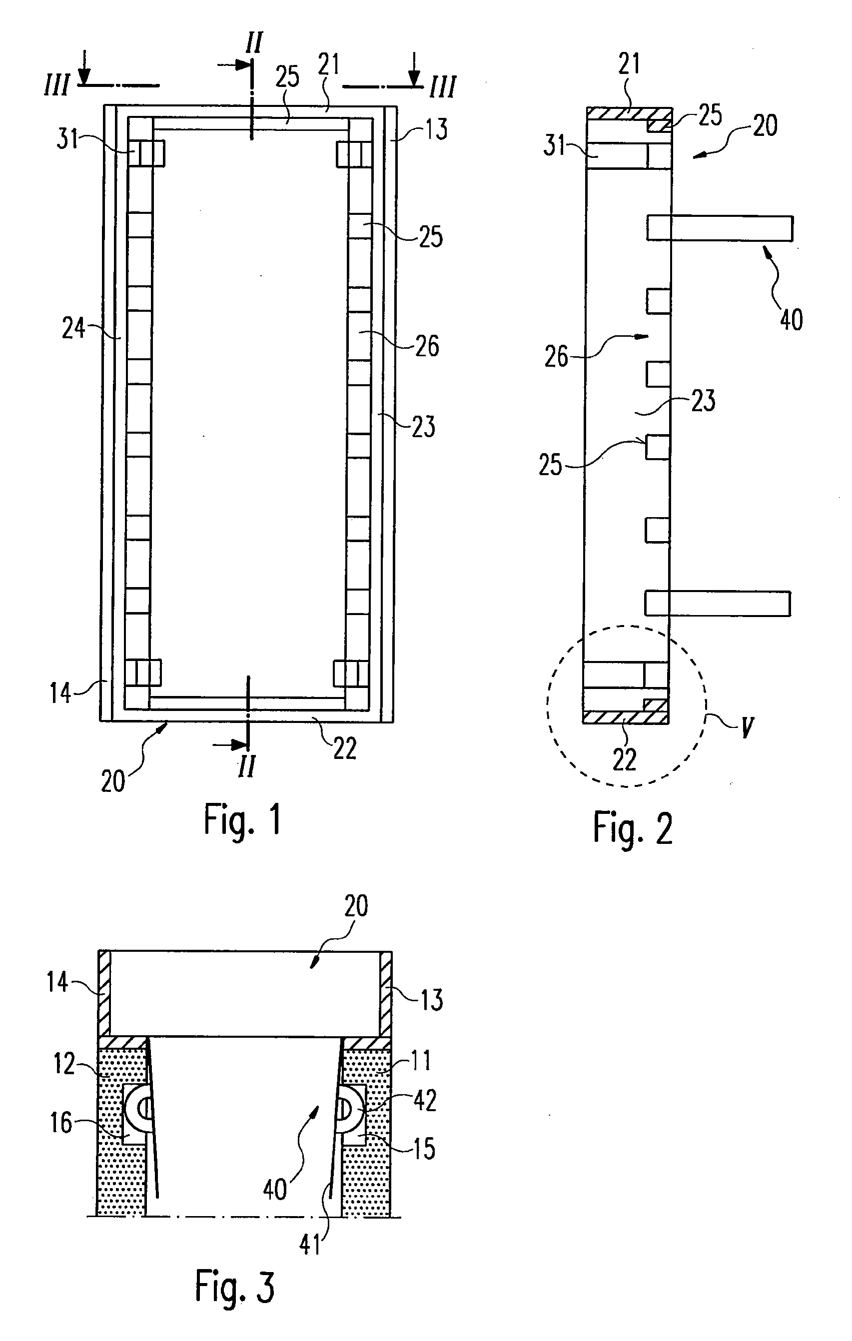
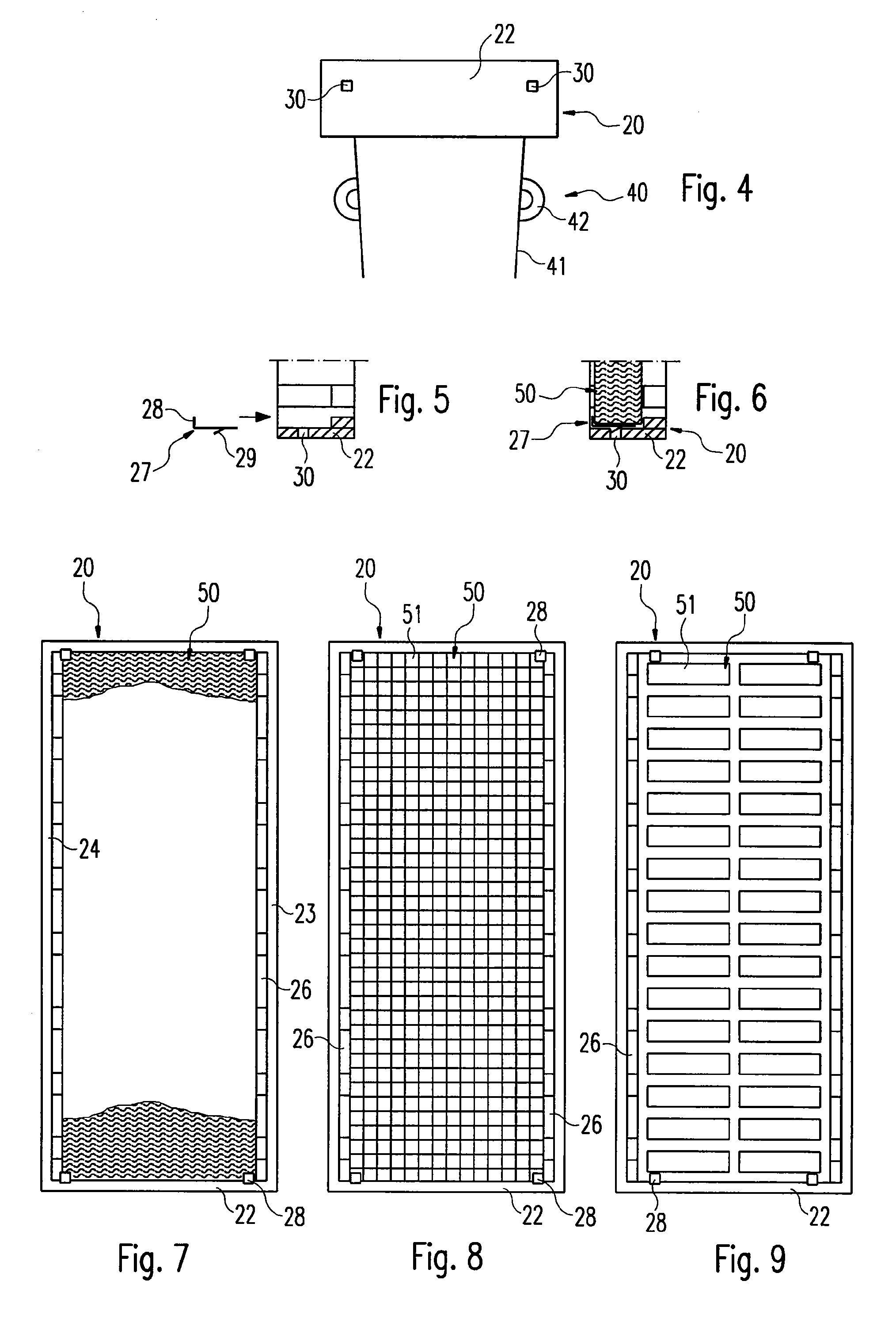
[0026]As shown in FIGS. 1-3, seated over the upper edges of side walls 11 and 12 is a channel 10 and casing 13, 14. In conventional drainage channels, a grating is located aid inside the casing. In the case of the embodiment of the invention shown here, a frame 20 is provided that has a front wall 21, a rear wall 22 and side walls 23, 24, which are solidly joined with one another. Supports 25 are provided, projecting from the walls 21-24 of the frame 20 towards the frame inner space, between which supports are outlet apertures 26.

[0027]Furthermore, fixing pieces 40 are attached to the side walls 23, 24 of the frame 20, which exhibit spring strips 41 and stop lugs 42 projecting outwards.

[0028]If the frame 20—as shown in FIG. 3—is inserted in a channel 10 between its walls 13, 14 respectively, the fixing pieces 40 protrude into the channel with their spring st...


PUM


Abstract

Covers for mounting onto upper edges of drainage channels or similar surface water drainage arrangements are well known, which are mounted onto the drainage channel by means of fixing devices. To simplify construction, storage and assembly it is proposed that the cover include a frame to which fixing means are attached and which includes devices for the retention and fixing of surface elements. The surface elements may be formed in various ways.

Description

CROSS-REFERENCE TO RELATED APPLICATIONS[0001]This application is a Section 371 of International Application No. PCT / EP2005 / 011032, filed Oct. 13, 2005, which was published in the German language on Apr. 27, 2006, under International Publication No. WO 2006 / 042695 A1 and the disclosure of which is incorporated herein by reference.BACKGROUND OF THE INVENTION[0002]The invention concerns a cover, in particular a grating or a plate for attaching to the upper edges of a drainage channel or similar surface drainage arrangement.[0003]To drain streets, public squares, entrances or similar surfaces drainage channels, gulley holes, site inlets etc are employed. Drainage channels will be discussed comprehensively for the sake of simplicity in the following explanation.[0004]Such drainage channels comprise a channel section, which is firmly embedded in the ground, and a cover, in particular a grating, that lies on the upper edges of the channel and is connected firmly to the channel by fixing de...

Claims


Application Information

Patent Timeline
IPC IPC(8): E03F5/06E03F5/14E02D29/14
CPCE03F5/06
Inventor MULLER, MICHAELSIEBER, MICHAEL
Owner ACO SEVERIN AHLMANN GMBH & CO KG
Why Eureka
Try Eureka