Reinforced balloon for a catheter

Inactive Publication Date: 2009-02-12
ANGIODYNAMICS INC
View PDF51 Cites 79 Cited by
  • Summary
  • Abstract
  • Description
  • Claims
  • Application Information

AI Technical Summary

Benefits of technology

[0011]A further aspect of this invention, also achieved by machine fabrication, is providing a reinforced balloon by a relatively rapid and low cost process.
[0012]Yet a further aspect of this invention is to provide a balloon having a des

Problems solved by technology

Some stenotic lesions can be highly resistant to opening at these pressures and occasionally standard balloon catheters are not strong enough to sufficiently open such lesions.
The method of manufacturing this balloon is time-consuming and requires separate steps to place the first and second fiber layers.
T

Method used


Image

  • Reinforced balloon for a catheter
  • Reinforced balloon for a catheter
  • Reinforced balloon for a catheter

Examples


Embodiment Construction

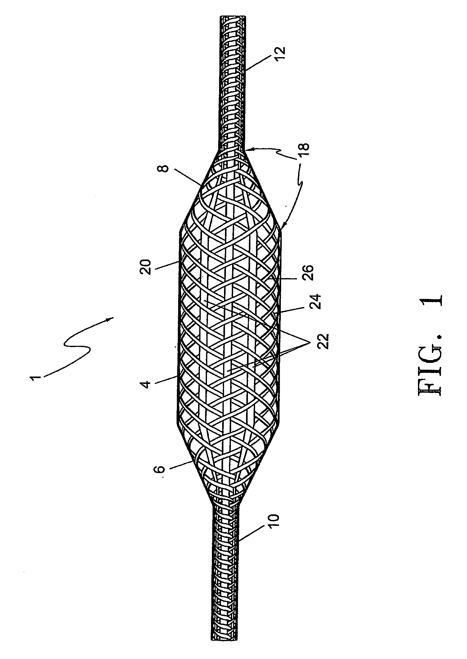
[0026]Referring to FIG. 1, a plan view of the reinforced balloon 1 is shown illustrating the interwoven multi-strand reinforcing ply or layer. The reinforced balloon 1 is comprised of proximal and distal balloon neck portions (10) and (12) respectively, proximal and distal balloon cone portions (6) and (8) respectively, and a balloon body portion (4). The distal and proximal balloon neck portions (10) and (12) are bonded to a catheter shaft (not shown) using bonding techniques commonly known in the art. The proximal and distal cone portions (6) and (8) gradually increase in diameter from the neck portions 10 / 12 diameter to the body portion (4) diameter. The balloon body portion (4) is designed to contact the vessel wall and when inflated is of a constant diameter.

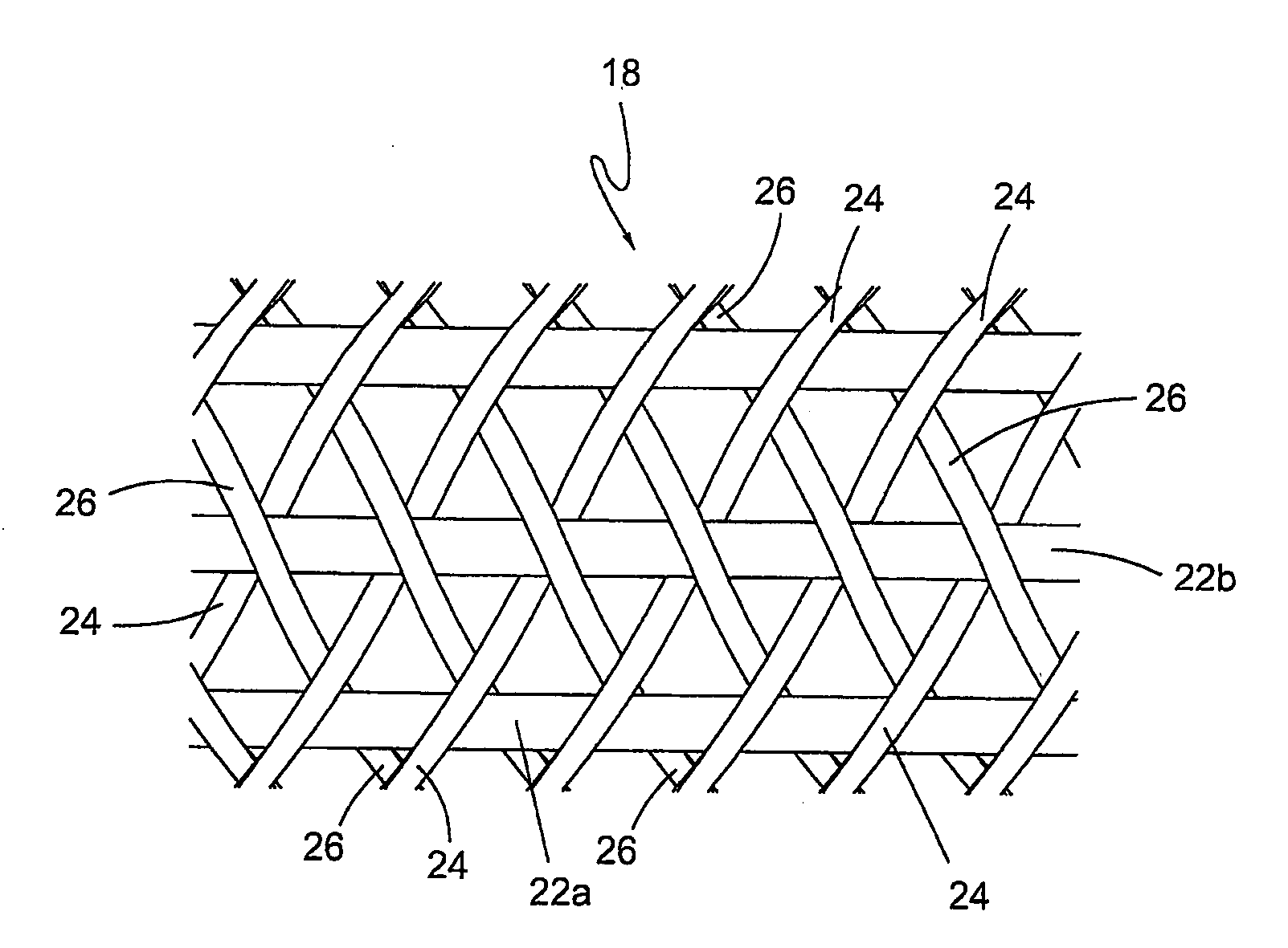
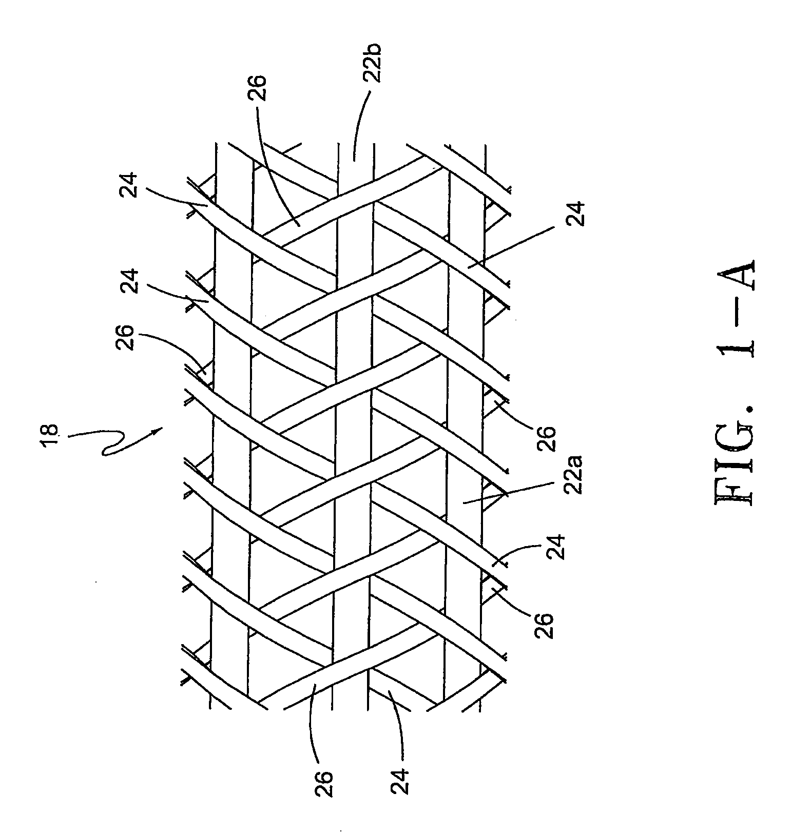
[0027]FIG. 1 illustrates the reinforcing ply (18), which is one of the four plies of material that comprise the laminate, reinforced balloon (1). This fiber ply (18) is applied directly to a base PET ply (14) (shown in FIG....


PUM

PropertyMeasurementUnit
Angleaaaaaaaaaa
Angleaaaaaaaaaa
Angleaaaaaaaaaa

Abstract

An inflatable balloon, and method of making same, for a medical catheter includes a base layer or non-compliant balloon substrate, a reinforcing layer, an adhesive. layer adhering the reinforcing layer to the non-compliant balloon substrate, and a top coat layer. The reinforcing layer is a single ply matrix of interwoven strands applied to the non-compliant balloon substrate. There are preferably three sets of strands in the single ply matrix. One set of strands extends in a longitudinal direction. Another set of strands extends circumferentially in a helical fashion with a clockwise orientation at an angle of approximately 65° with the strands that extend in the longitudinal direction. The third set of strands extends circumferentially in a helical fashion with a counter-clockwise orientation at an angle of approximately 65° with the strands that extend in the longitudinal direction. The three sets of strands are interwoven with one another by a braiding machine so as to provide a single ply of interwoven strands to achieve a uniform, reproducible reinforcing matrix.

Description

CROSS REFERENCE TO RELATED APPLICATIONS[0001]This application claims priority to U.S. Provisional Application No. 60 / 651,696, filed Feb. 9, 2005, which is hereby incorporated herein by reference.FIELD OF THE INVENTION[0002]The present invention relates to a reinforced high strength balloon adapted for use on a catheter and more particularly adapted for use on a percutaneous transluminal angioplasty catheter.BACKGROUND OF THE INVENTION[0003]Treatment of stenosis by angioplasty balloon catheters is well known. Typically a lesion is opened by inflating a balloon catheter at moderate inflation pressures up to 18-20 atms. Some stenotic lesions can be highly resistant to opening at these pressures and occasionally standard balloon catheters are not strong enough to sufficiently open such lesions. For example, when treating a stenosis that occurs at the venous anastomosis of a dialysis graft, it is found that often these lesions may require pressure in excess of 30 atmospheres to sufficien...

Claims


Application Information

Patent Timeline
IPC IPC(8): A61M25/10B32B37/06C09J5/06A61F2/958
CPCA61M25/10A61M25/1029A61M2025/1084A61M25/104A61M25/1034
Inventor WENG, ADELAPPLING, WILLIAM M.
Owner ANGIODYNAMICS INC
Why Eureka
Try Eureka