Filament Winding Automated System

an automated system and filament technology, applied in the direction of inductance/transformer/magnet manufacture, transportation and packaging, other domestic articles, etc., can solve the problems of increasing costs, reducing total production efficiency, and reducing the time required for operations, so as to increase production efficiency and reduce costs

Active Publication Date: 2009-02-12
MURATA MASCH LTD
View PDF11 Cites 34 Cited by
  • Summary
  • Abstract
  • Description
  • Claims
  • Application Information

AI Technical Summary

Benefits of technology

[0006]In view of the above-described problems, an object of the present invention is to provide a filament winding automated system that enables an increase in production efficiency and a reduction in costs.
[0013]Therefore, compared to conventional filament winding devices, the filament winding automated system according to the present invention allows almost all of the production line to be automated to sharply reduce the number of operations performed by the operator and the time required for the operations, enabling an increase in production efficiency and a reduction in labor and costs required.

Problems solved by technology

Disadvantageously, with an increase in the time required for operations performed by the operator and in the number of the operations, total production efficiency may decrease to increase costs.

Method used


Image

  • Filament Winding Automated System
  • Filament Winding Automated System
  • Filament Winding Automated System

Examples


first embodiment

First, a first embodiment will be described.

[General Configuration]

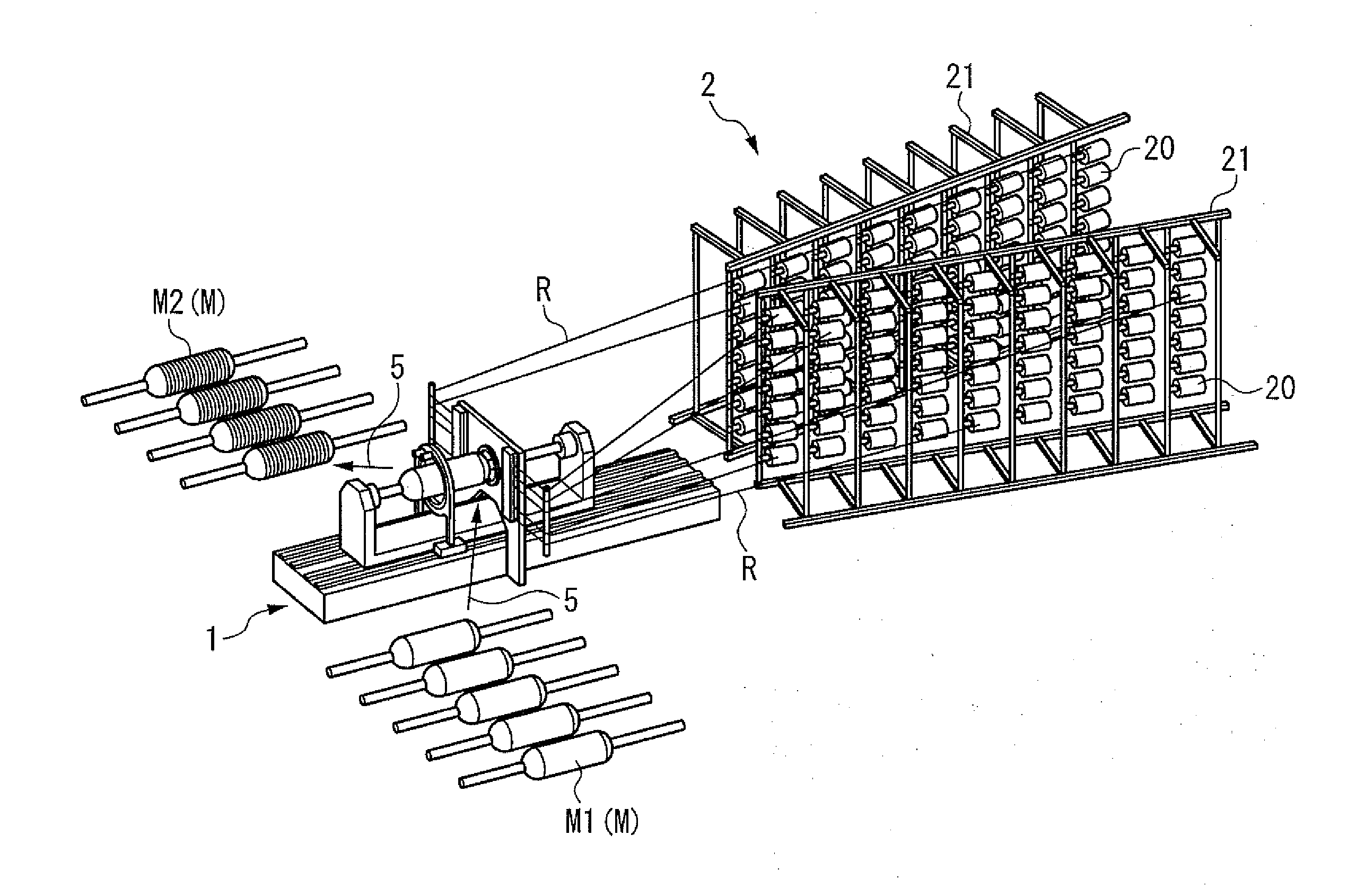
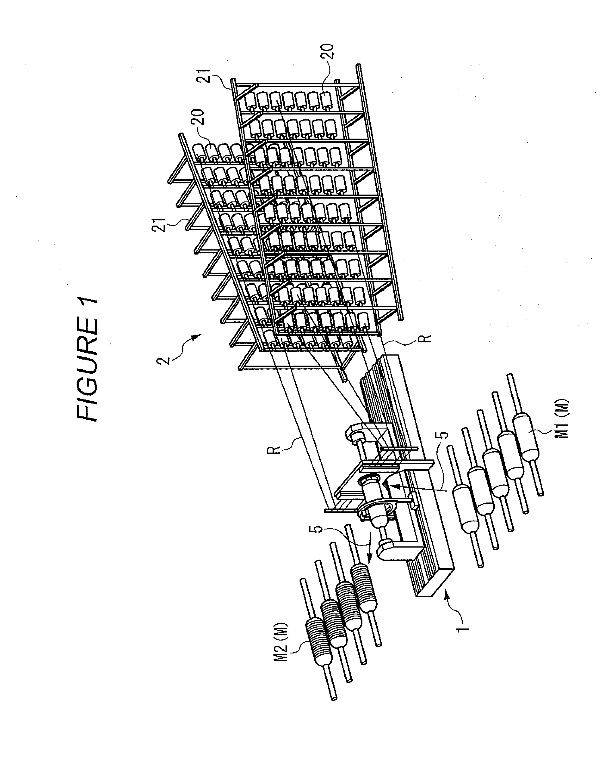
[0046]FIG. 1 is a partly omitted perspective view showing a filament winding automated system according to a first embodiment. The filament winding automated system comprises a winding device 1 and a supply portion 2.

[0047]The winding device 1 winds a fiber bundle R around a mandrel M. The supply portion 2 comprises support portions 21, 21, and a plurality of creels 20 in each of the creel support portions 21, 21. The fiber bundle B is wound around and housed on each of the creels 20.

[0048]A fiber bundle R is made of, for example, a textile material formed using a textile material such as glass fibers and a synthetic resin. The supply portion 2 supplies the fiber bundle R drawn out from each creel 20 to the winding device 1.

[0049]The fiber bundle R is pre-impregnated with a thermosetting synthetic resin material. The fiber bundle R may not be impregnated with any resin. In this case, a resin impregnating device (not ...

second embodiment

[0117]Now, a second embodiment will be described. A detailed description will be given of arrangements of the second embodiment which are different from the corresponding ones of the first embodiment (arrangements of the second embodiment are the same as the corresponding ones of the first embodiment unless otherwise specified).

[General Configuration]

[0118]FIG. 14 is a partly omitted perspective view showing a filament winding automated system according to the second embodiment. A plurality of the mandrels (M1, M2) are arranged on each of the opposite sides (the side closer to the reader and the side farther from the reader) of the winding device 1. In the second embodiment, the mandrels M (M1, M2) are arranged on each of one end side (in the left of the figures) and other end side (in the right of the figures) of the winding device 1.

[Winding Device]

[0119]FIG. 15 is an enlarged perspective view showing the winding device shown in FIG. 14. The winding device 1 comprises two hoop win...


PUM

PropertyMeasurementUnit
angleaaaaaaaaaa
strengthaaaaaaaaaa
shapeaaaaaaaaaa

Abstract

The present invention makes it possible to increase production efficiency while reducing costs. A filament winding automated system according to the present invention includes a winding device winding a fiber bundle R paid out from a head portion 12, 13, around a mandrel M1, an installing device 5 installing the mandrel around M1 which no fiber bundle has been wound yet, at a winding position, a discharging device 5 discharging the mandrel around which the fiber bundle has already been wound, from the winding position, a delivery device 3 holding and delivering the fiber bundle R from the mandrel around which the fiber bundle has already been wound to a mandrel M1 around which no fiber bundle has been wound yet, and a cutting device cutting the fiber bundle R, and after winding is completed, the delivery device 3 holds the fiber bundle R paid out from the head portion 12, 13, the cutting device cuts and separates the fiber bundle R from the mandrel around which the fiber bundle has already been wound, the discharging device 5 discharges the mandrel around which the fiber bundle has already been wound, the installing device installs the mandrel M1 around which no fiber bundle has been wound yet, and the winding device starts winding the fiber bundle R held by the delivery device 3, around the mandrel M1 around which no fiber bundle has been wound yet.

Description

FIELD OF THE INVENTION[0001]The present invention relates to a filament winding automated system having an automated production line based on a filament winding method.BACKGROUND OF THE INVENTION[0002]A filament winding device is a device that manufactures hollow containers such as pressure tanks or pipes on the basis of a filament winding method (see, for example, the Japanese Patent Application (Tokugan) No. 2007-34723 and the Japanese Patent Application Publication (Tokkai-Hei) No. 10-119138). The filament winding method manufactures products (pressure tanks or the like) by winding a fiber bundle around a mandrel (liner). The fiber bundle is made of, for example, a textile material formed using a textile material such as glass fibers and a synthetic resin.[0003]The filament winding device winds a fiber bundle paid out from a head portion, around a mandrel. The head portion is composed of a hoop winding head that winds the fiber bundle around the mandrel in hoop form, and a helica...

Claims


Application Information

Patent Timeline
Patent Type & Authority Applications(United States)
IPC IPC(8): B65H81/08
CPCB29C53/602B29L2031/7156B29C53/828
Inventor UOZUMI, TADASHITAKASHIMA, HIROKITANIGAWA, MOTOHIRO
Owner MURATA MASCH LTD
Why Eureka
Try Eureka