Electric current conduction system for appliance

a current conduction system and electric current technology, applied in the field of electric current conduction system, can solve the problems of electrical supply wires and/or wire blocks being strained or even damaged, and achieve the effect of reducing the risk of electrical shock

Inactive Publication Date: 2009-02-12
ELECTROLUX HOME PROD CORP NV
View PDF43 Cites 53 Cited by
  • Summary
  • Abstract
  • Description
  • Claims
  • Application Information

AI Technical Summary

Benefits of technology

[0004]The following presents a simplified summary of the invention in order to provide a basic understanding of some aspects of the invention. This summary is not an extensive overview of the invention. It is intended to identify neither

Problems solved by technology

Further, the electrical supply wires and/or wire blocks can become strained or even damaged due to the repeti

Method used


Image

  • Electric current conduction system for appliance
  • Electric current conduction system for appliance
  • Electric current conduction system for appliance

Examples


Embodiment Construction

[0017]An example embodiment of a device that incorporates aspects of the present invention is shown in the drawings. It is to be appreciated that the shown example is not intended to be a limitation on the present invention. For example, one or more aspects of the present invention can be utilized in other embodiments and even other types of devices.

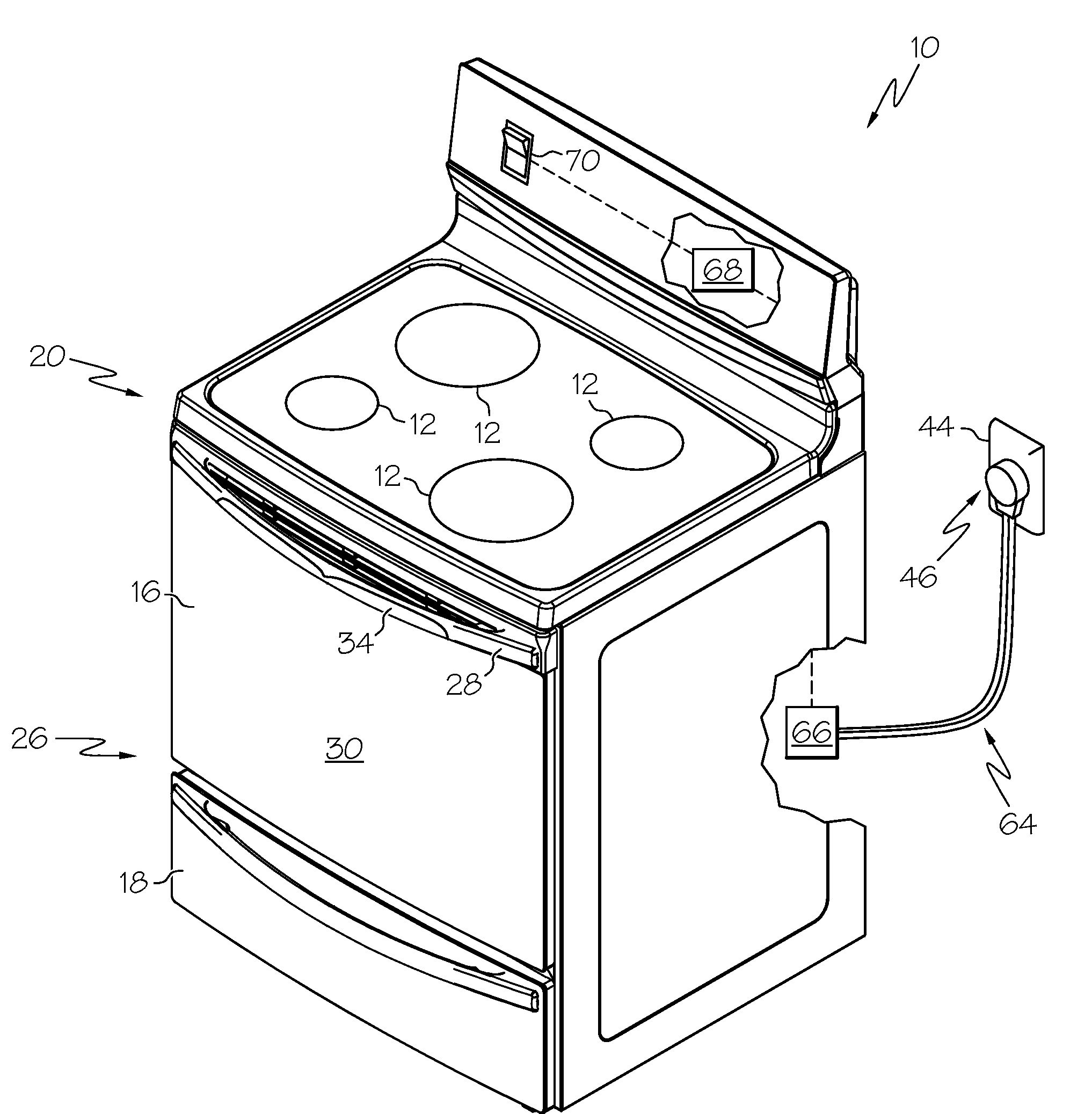
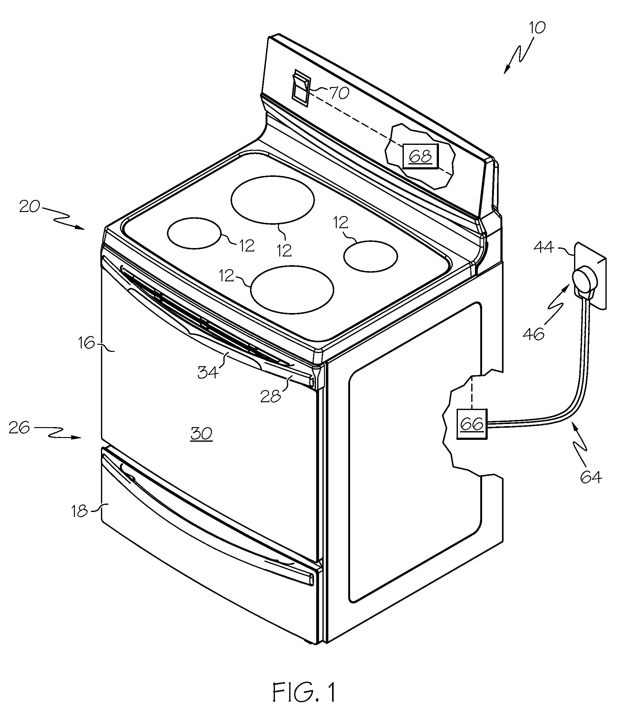
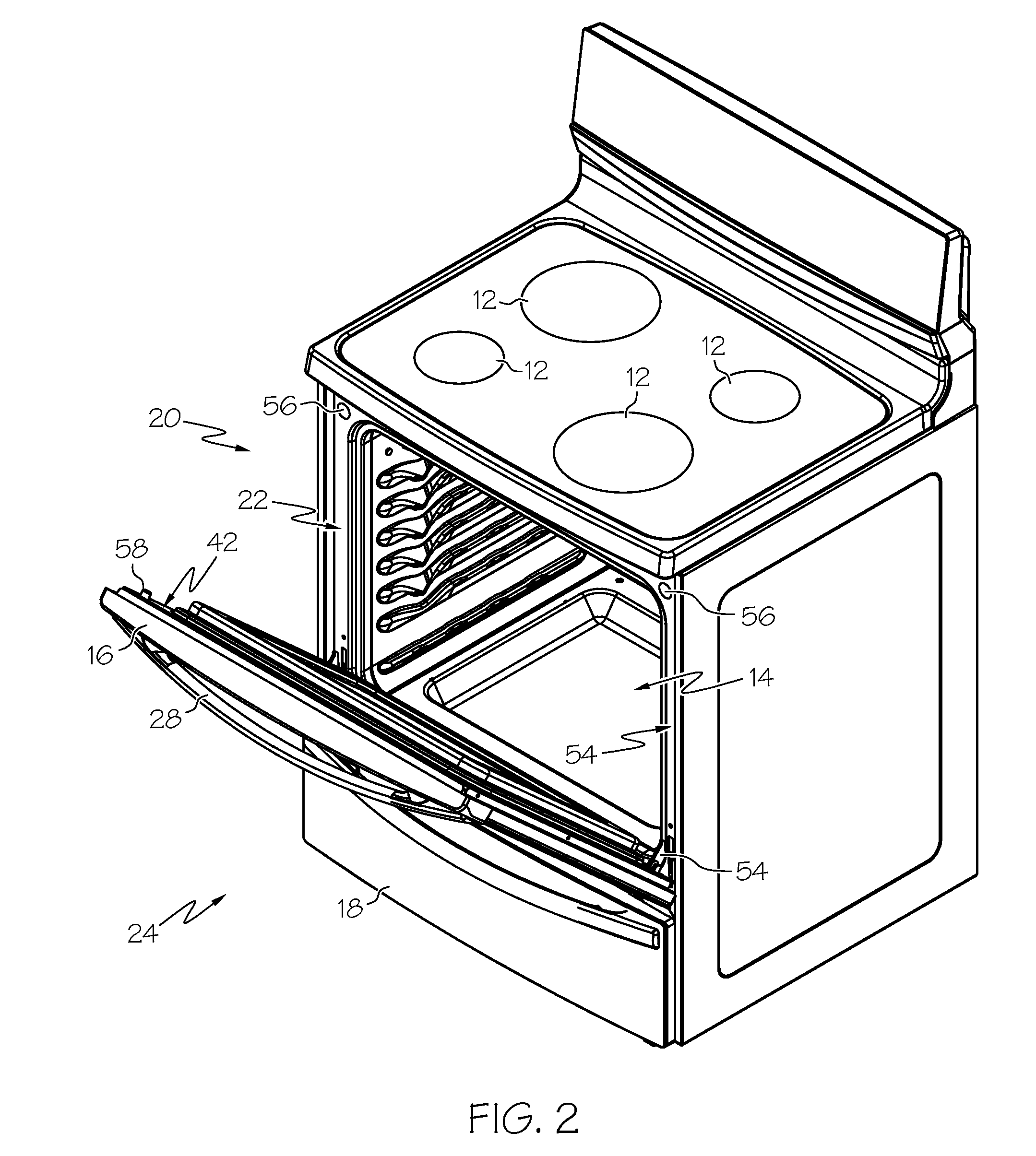
[0018]Turning initially to FIG. 1, an example appliance 10 having an electric current conduction system is illustrated in accordance with an aspect of the present invention. As shown, the appliance 10 can be a cooking range, though various other appliances having doors can also be used. The range 10 can include various common elements, such as one or more burners 12 located on a top surface thereof, an internal oven cavity 14 (see FIG. 2) selectively closed by an oven door 16, and / or a warming / storage drawer 18. As can be appreciated, any of the burners 12 and / or the oven cavity 14 can be electric or gas powered. In addition or alternati...


PUM


Abstract

An appliance is provided with an electric current conduction system. The appliance includes a main body portion including an interior cavity, and a door mounted for movement between an open position and a closed position. A driven component is coupled to the door and disposed at least partially exterior of an outer face thereof. In one example, the driven component is a light. An electric current conduction system includes a first conductor connected to the main body a second conductor connected to the door and configured to selectively engage the first conductor based upon the position of the door. Electric current is conducted between the first and second conductors when the first conductor is enaged with the second conductor. The driven component is operatively connected to the second conductor, such that electric current is conducted between the main body portion and the driven component for driving the driven component.

Description

RELATED APPLICATIONS[0001]Not Applicable.FIELD OF THE INVENTION[0002]The present invention relates generally to an electric current conduction system for an appliance, and more particularly to an electric current conduction system for selectively driving a driven component of an appliance.BACKGROUND OF THE INVENTION[0003]Several types of appliances, such as ranges, dishwashers, refrigerators, freezers, etc., may include various driven components that are selectively driven via automatic or manual controls. Electric current is often supplied to the driven components by multitudes wires routed variously throughout the appliance, many of which must be connected by way of wire blocks, junctions, or the like. Often, where a driven component is located on an appliance door, the electrical supply wires must also be routed through the door hinges or in other inconvenient manners so as not to be exposed when the door is opened. Further, the electrical supply wires and / or wire blocks can beco...

Claims


Application Information

Patent Timeline
IPC IPC(8): H05B1/00
CPCF24C7/08F24C15/02F24C15/008
Inventor BOUTWELL, RODNEY
Owner ELECTROLUX HOME PROD CORP NV
Why Eureka
Try Eureka