System for determining the nominal voltage of a power supply

a power supply and nominal voltage technology, applied in the direction of ohmic-resistance heating, electrical heating, electrical apparatus, etc., can solve the problem of not being easy to use in some applications

Active Publication Date: 2009-02-12
COPRECITEC
View PDF27 Cites 47 Cited by
  • Summary
  • Abstract
  • Description
  • Claims
  • Application Information

AI Technical Summary

Problems solved by technology

Although the closed-loop temperature control is effective, it is not easy to use in some applications, such as cooker hob heat sources.

Method used


Image

  • System for determining the nominal voltage of a power supply
  • System for determining the nominal voltage of a power supply
  • System for determining the nominal voltage of a power supply

Examples


Embodiment Construction

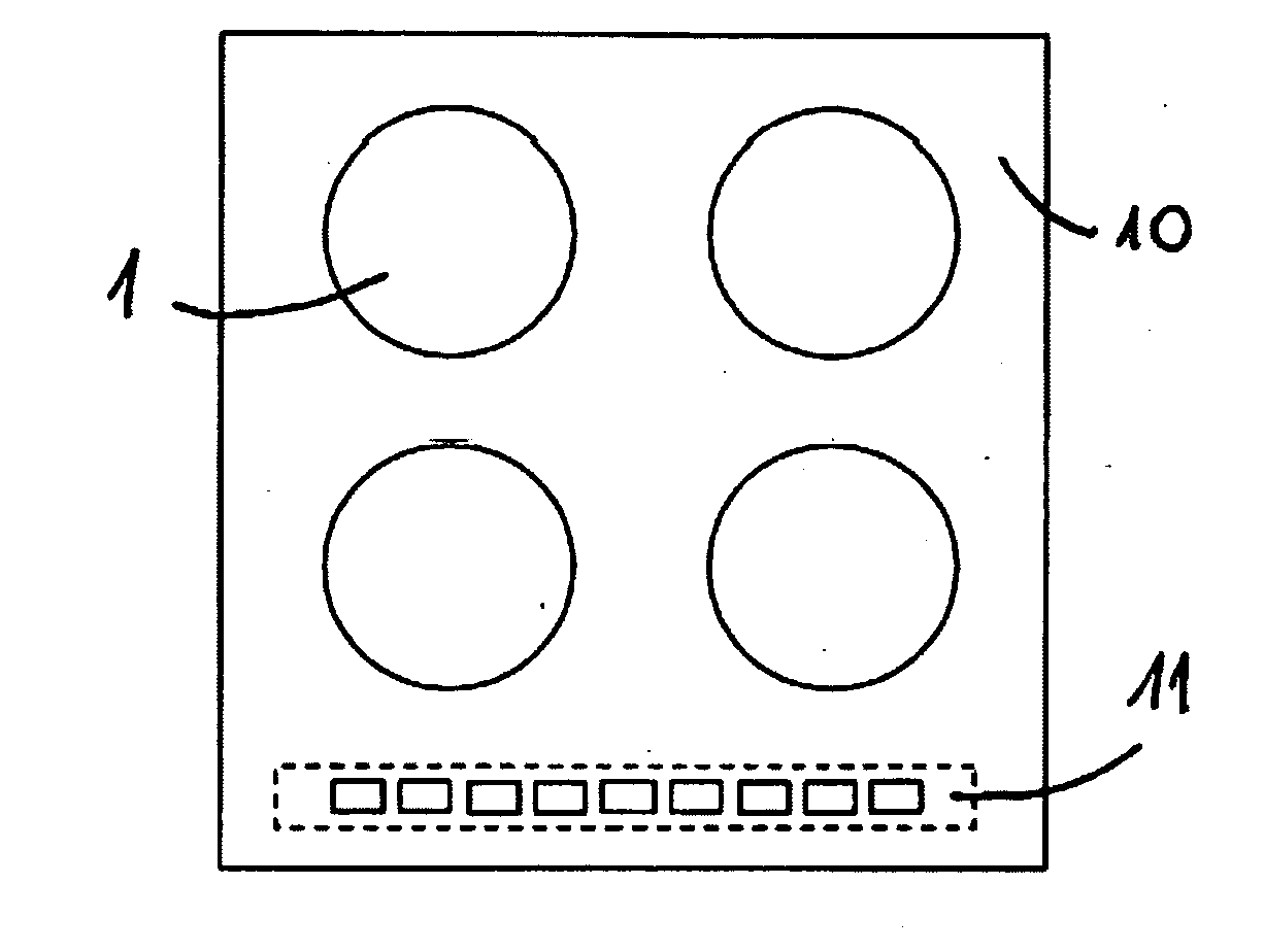
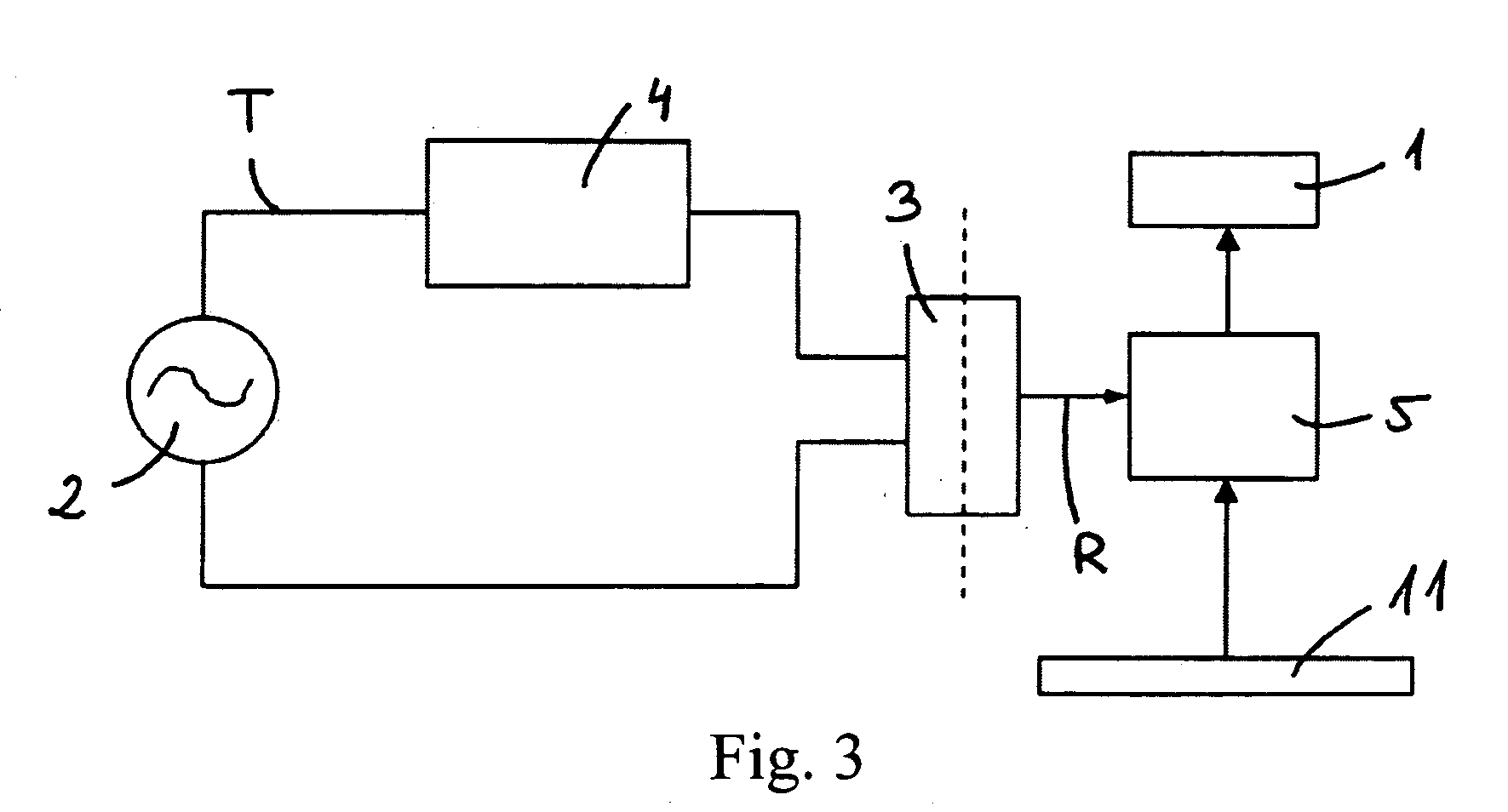
[0022]According to an aspect of the present invention, a system is provided to determine the nominal voltage of an external multi-phase power supply 2, and thereby control the power supplied to at least one heat source 1 connected to the power supply 2, and therefore to control the output temperature of the heat source 1, it being appropriately regulated regardless of the value of the nominal voltage. With reference to FIG. 1, the heat source 1 may be a part of a cooker hob 10 for example, the system comprising a user interface 11 so that a user may select the power required in the heat source 1. The system also comprises a controller / control means 5 that modify the work cycle of a square power signal corresponding to the heat source 1 in accordance with the power required by the user, thus increasing the width of the positive pulse of the power signal if more power is required, or decreasing it if the reverse is required.

[0023]The power supply 2 is an alternating voltage supply tha...


PUM


Abstract

A system and method for controlling the output power of a heat source. The system includes a user interface so that a user may select the power required from the heat source, a power supply, and a controller that receives a rectified signal having a work ratio that corresponds to a nominal voltage of an alternating voltage signal corresponding to a phase of a power supply. The controller is configured to control the output power of the heat source in accordance with the power selected by the user, and modifies, if necessary, the work cycle of a power signal linked to the heat source in accordance with the work ratio in order to compensate possible differences in the nominal voltage between different power supplier.

Description

CROSS-REFERENCE TO RELATED APPLICATIONS[0001]This application claims priority to Spanish Patent Application ES-P200702210, filed Aug. 6, 2007.TECHNICAL FIELD[0002]The present invention relates to systems for determining the nominal voltage of a power supply, and more specifically to systems for determining the nominal voltage of the power supply of domestic appliances, particularly heat sources, so that the control of power linked to a heat source may be adjusted in accordance with the nominal voltage that is determined.BACKGROUND[0003]The most widely used method for controlling the temperature of a heat source (linked to a specific power) is to use a closed-loop control in which the temperature of a heat source or its surroundings is determined by a temperature sensor, and in which an automatic control is used to adjust the power of the heat source for the purposes of reaching and maintaining the required temperature. A thermostat may be used for this purpose, for example. Although...

Claims


Application Information

Patent Timeline
Patent Type & Authority Applications(United States)
IPC IPC(8): H05B3/02
CPCH05B1/0266
Inventor LLONA, GONZALO FERNANDEZ
Owner COPRECITEC
Why Eureka
Try Eureka