CPAP Hose Support System

a technology of cpap hoses and support systems, which is applied in the direction of machine supports, respirators, other domestic objects, etc., can solve the problems of reducing oxygen in the blood, arousing from sleep, and potential damage from falling on the floor, and achieves the effect of convenient disassembly and attachment to the bed

Inactive Publication Date: 2009-02-12
HBG PARTNERS
View PDF47 Cites 14 Cited by
  • Summary
  • Abstract
  • Description
  • Claims
  • Application Information

AI Technical Summary

Benefits of technology

[0015]An object is to provide a CPAP tubing support system for reducing user contact with the CPAP tubing of a CPAP machine.
[0023]A further object is to provide a CPAP tubing support system that maintains the CPAP tubing in a substantially constant position by engaging the ridges of the CPAP tubing.

Problems solved by technology

The reduced oxygen to the lungs results in a reduction of oxygen in the blood thereby causing arousal from sleep.
One of the main problems with conventional CPAP machines is that the CPAP tubing can cause irritation or arousal to the user during sleep resulting in discomfort.
Another problem is that the CPAP tubing may be pulled by the user during their sleep which can move the flow generator resulting in potential damage from dropping on the floor.
Another problem is that the pulling upon the CPAP tubing can result in dislodging of the interface from the user's face thereby reducing the effectiveness of the CPAP machine.

Method used


Image

  • CPAP Hose Support System
  • CPAP Hose Support System
  • CPAP Hose Support System

Examples


Embodiment Construction

A. Overview.

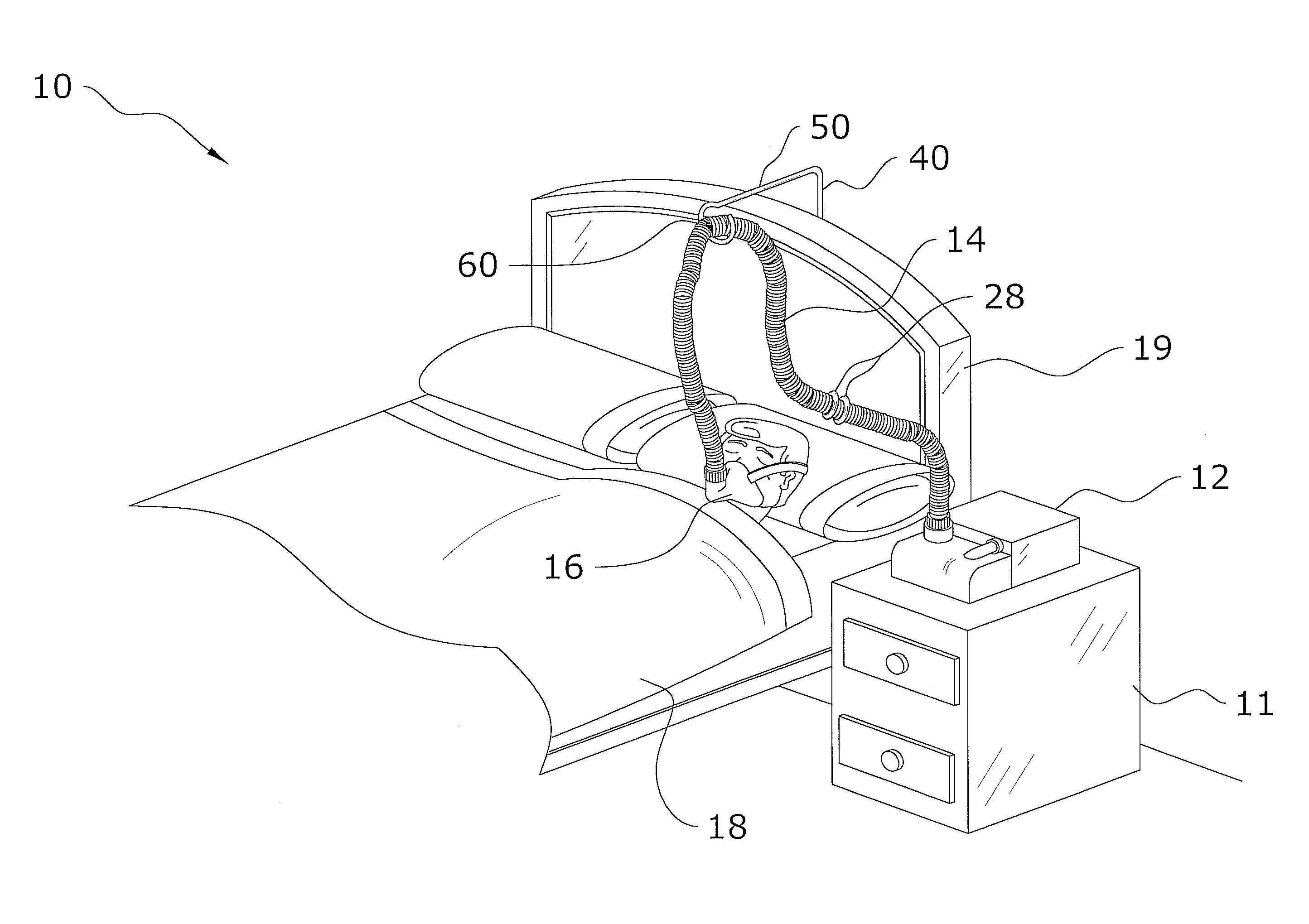
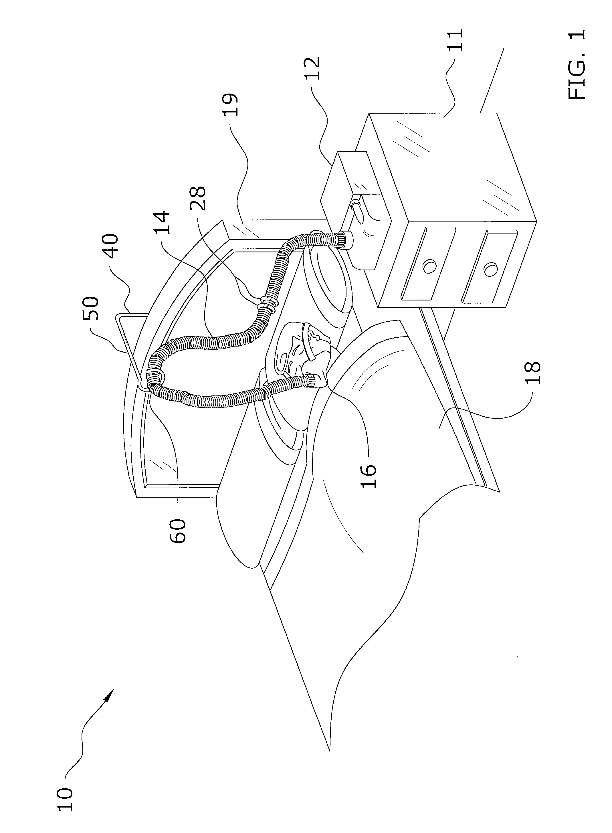
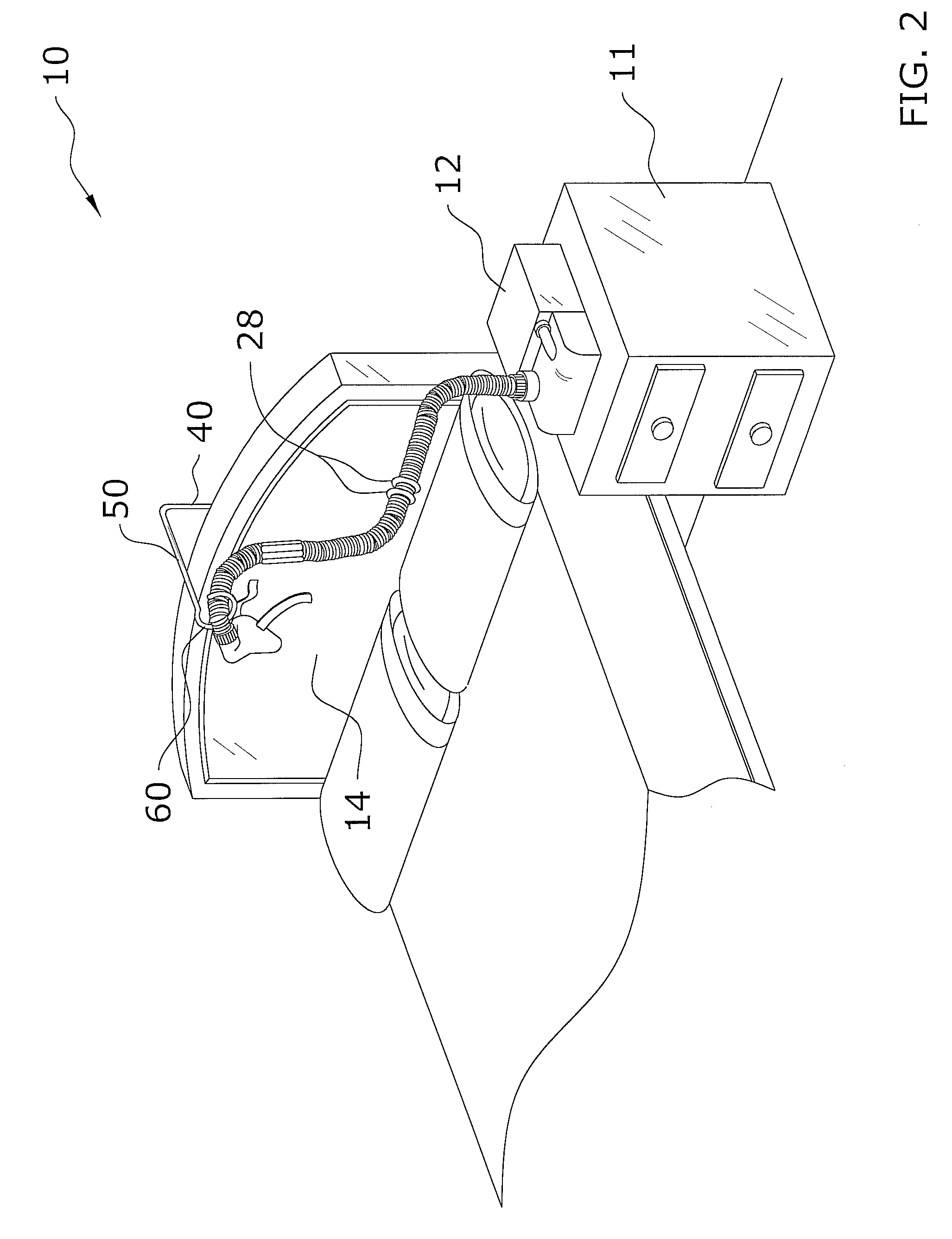
[0038]Turning now descriptively to the drawings, in which similar reference characters denote similar elements throughout the several views, FIGS. 1 through 11 illustrate a CPAP tubing support system 10, which comprises a base, a vertical member 40 attached to the base, a horizontal member extending from an upper end of the vertical member 40, and a support member 60 attached to a distal end of the horizontal member for receiving a CPAP tubing 14 from a CPAP machine. The support member 60 may include a slot 62 and a receiver opening 64 for receiving the CPAP tubing 14. The support member 60 preferably is comprised of a substantially circular shape for engaging the ribs of the CPAP tubing 14 in a relatively non-moving manner. The vertical member 40 is preferably rotatably connected to the base.

B. CPAP Machine.

[0039]FIGS. 1 and 2 illustrate a conventional CPAP machine. A conventional CPAP machine includes an interface 16 (e.g. nasal pillow, nose mask or full-face mask), a ...


PUM


Abstract

A CPAP tubing support system for reducing user contact with the CPAP tubing of a CPAP machine. The CPAP tubing support system generally includes a base, a vertical member attached to the base, a horizontal member extending from an upper end of the vertical member, and a support member attached to a distal end of the horizontal member for receiving a length of CPAP tubing from a CPAP machine. The support member includes a slot and a receiver opening for receiving the CPAP tubing. The support member preferably is comprised of a substantially circular shape for engaging the ribs of the CPAP tubing in a relatively non-moving manner while still allowing the CPAP tubing to extend or retract when the user is active in bed. The vertical member is preferably rotatably connected to the base.

Description

CROSS REFERENCE TO RELATED APPLICATIONS[0001]I hereby claim benefit under Title 35, United States Code, Section 119(e) of U.S. provisional patent application Ser. No. 60 / 955,061 filed Aug. 10, 2007. The 60 / 955,061 application is currently pending. The 60 / 955,061 application is hereby incorporated by reference into this application.STATEMENT REGARDING FEDERALLY SPONSORED RESEARCH OR DEVELOPMENT[0002]Not applicable to this application.BACKGROUND OF THE INVENTION[0003]1. Field of the Invention[0004]The present invention relates generally to continuous positive airway pressure (“CPAP”) machines and more specifically it relates to a CPAP tubing support system for reducing user contact with the CPAP tubing of a CPAP machine.[0005]2. Description of the Related Art[0006]Any discussion of the related art throughout the specification should in no way be considered as an admission that such related art is widely known or forms part of common general knowledge in the field.[0007]Sleep apnea occ...

Claims


Application Information

Patent Timeline
Patent Type & Authority Applications(United States)
IPC IPC(8): F16L3/00
CPCF16L3/127F16L3/1218A61G7/0503A61M16/0875A61M2209/082
Inventor YATES, STEVEN T.SHRIVASTAVA, DEEPAK K.
Owner HBG PARTNERS
Why Eureka
Try Eureka