Changeover device of pull cord control and wireless remote control for a DC brushless-motor ceiling fan

a technology of wireless remote control and ceiling fan, which is applied in the direction of programme control, dynamo-electric converter control, instruments, etc., can solve the problems of wasting labor and time, and inconvenience, and achieve the effect of avoiding danger and facilitating installation

Active Publication Date: 2009-02-12
AIR COOL INDAL
View PDF2 Cites 134 Cited by
  • Summary
  • Abstract
  • Description
  • Claims
  • Application Information

AI Technical Summary

Benefits of technology

[0006]The objective of this invention is to offer a changeover device of pull cord control and wireless remote control for a DC brushless-motor ceiling fan, mainly including a driver and a connector. The driver positioned in the interior of a ceiling fan basic body is provided with a detecting unit for detecting whether or not the connector inside a hanging bell is connected with a wireless-controlled switch unit. When detecting that the connector is already connected with the wireless-controlled switch unit, the detecting unit will send back a control signal to a micro-processor and at this time, the micro-processor will only receive control signals coming from a wireless remote-controlled unit instead of receiving control signals coming from a pull cord controlled unit. Further, the connector is installed inside the hanging bell; therefore, when the DC brushless-motor ceiling fan is expected to have a function of remote control, it is only necessary to have a wireless-controlled switch unit assembled inside the hanging bell and connected with the connector therein, facilitating installation and avoiding danger caused by improper assembly.

Problems solved by technology

Subsequently, fittings of the remote-controlled switch are secured on the controller 4 and then, the controller 4 and the ceiling fan can be assembled anew, thus resulting in much inconvenience, wasting labor and time and increasing danger caused by improper re-installation of the ceiling fan.

Method used


Image

  • Changeover device of pull cord control and wireless remote control for a DC brushless-motor ceiling fan
  • Changeover device of pull cord control and wireless remote control for a DC brushless-motor ceiling fan
  • Changeover device of pull cord control and wireless remote control for a DC brushless-motor ceiling fan

Examples


Embodiment Construction

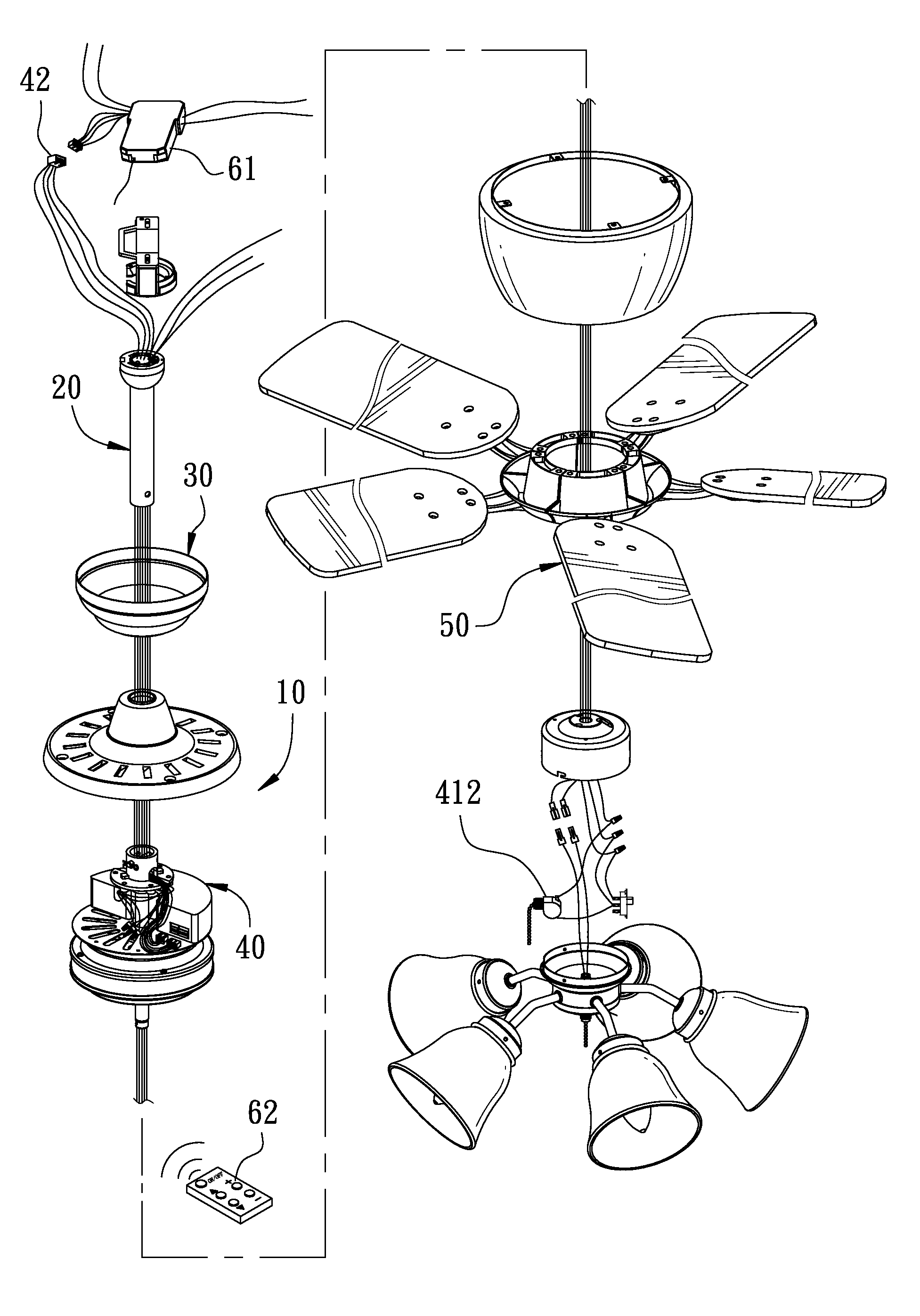
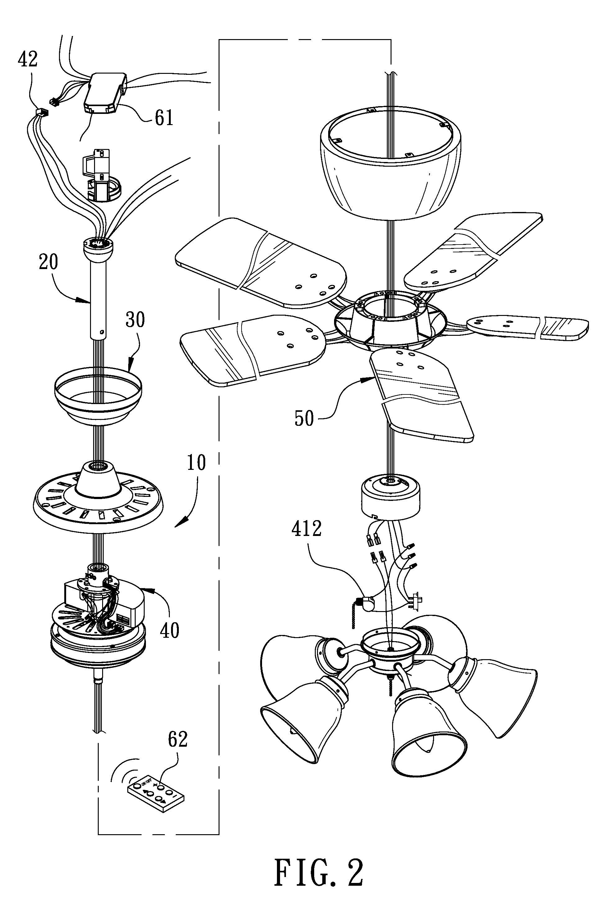
[0013]A first preferred embodiment of a change-over device of pull cord control and wireless remote control for a DC brushless-motor ceiling fan in the present invention, as shown in FIG. 2, includes a ceiling fan basic body 10 positioned at a free end of a DC brushless-motor ceiling fan. The ceiling fan basic body 10 has one end connected with an extension tube 20 pivotally disposed in a hanging bell 30 at a fixed end of the DC brushless-motor ceiling fan. The changeover device 40 of pull rope control and wireless remote control consists of a driver 41 and a connector 42.

[0014]The driver 41 installed in the interior of the ceiling fan basic body 10 is composed of a microprocessor 411, a pull cord-control unit 412, a wireless remote-control unit 413, a driving unit 414 and a detecting unit 415 on a printed circuit board. The microprocessor receives, processes, operates and chooses control signals received by one end and coming from the pull cord-control unit 412, or coming from the ...


PUM


Abstract

A change-over device of pull cord control and wireless remote control for a DC brushless-motor ceiling fan is to have a driver installed in a ceiling fan basic body, and the driver has a detecting unit for detecting whether or not a connector positioned in a hanging bell is connected with a wireless control switch unit so as to control the blades of the DC brushless-motor ceiling fan to rotate by pull cord control or by wireless remote control. Further, the connector is installed inside the hanging bell; therefore, when the DC brushless-motor ceiling fan is to be additionally provided with a wireless control switch unit, it is convenient and safe in installation.

Description

BACKGROUND OF THE INVENTION[0001]1. Field of the Invention[0002]This invention relates to a changeover device, particularly to one used for changing over pull cord control and wireless remote control for a DC brushless-motor ceiling fan.[0003]2. Description of the Prior Art[0004]A conventional ceiling fan, as shown in FIG. 1, includes a basic body 1 positioned at a free end of the ceiling fan. The basic body 1 of the ceiling fan has one end connected with an extension tube 2 pivotally disposed inside a hanging bell 3 at a fixed end of the ceiling fan. The basic body 1 of the ceiling fan is provided in the interior with a controller 4 and a driving motor 5, and the controller 4 has one end connected with a pull cord-controlled switch 6 for operating the controller 4 to drive the driving motor 5 to turn the ceiling fan blades 7 that are pivotally fixed on the driving motor 5.[0005]However, the conventional ceiling fan is to have the pull cord-controlled switch 6 to turn on or off the ...

Claims


Application Information

Patent Timeline
Patent Type & Authority Applications(United States)
IPC IPC(8): H02P7/00
CPCF04D25/088
Inventor TANG, YUNG YU
Owner AIR COOL INDAL
Why Eureka
Try Eureka