Acoustic ear tube retainer spring

a technology for acoustic hearing and retainer springs, which is applied in the field of metal retainer springs for acoustic hearing tubes, can solve the problems of pressure and slippage, soft ear pieces have a problem with retention, and do not securely hold the ear pieces in place, so as to eliminate pressure and eliminate slippage

Inactive Publication Date: 2009-02-12
DAVIS JOHN W
View PDF2 Cites 17 Cited by
  • Summary
  • Abstract
  • Description
  • Claims
  • Application Information

AI Technical Summary

Benefits of technology

[0031]An advantage of the present invention is that it retains the acoustic ear tube securely in place without slippage in a portion of the ear canal which does not cause discomfort.
[0032]Another advantage of the present invention is that it and admits air and sound into the inner ear.
[0033]One more advantage of the present invention is that it eliminates pressure from snug fitting plastic devices and eliminate the slippage that is the most prevalent problem.
[0034]An additional advantage of the present invention is that it is made in a variety sizes to accommodate various different ear canal sizes.
[0035]A further advantage of the present invention is that it is more durable than other in-the-ear devices.
[0036]A contributory advantage of the present invention is that it is more adjustable than current in-the-ear devices.

Problems solved by technology

Most of the soft ear pieces have a problem with retention.
They are made to be soft so that they will fit into the ear without causing discomfort or irritation, but often do not hold the ear piece securely in place.
The biggest problem with this style of aid is to get the tube to stay within the ear canal.
Pressure and slippage are problems with snug fitting plastic devices.
Most of the soft ear pieces have a problem with retention.
If the mold is too tight within the ear canal, it can cause irritation or discomfort.
If the mold is made without enough airflow, the user's voice will sound muffled and distorted.
If the device is too loose, the mold can slip out of position.
Molds out of position can cause feedback: (a high pitch whistle), and the aid will become more conspicuous because of noise the aid is generating.
If the mold works it way out of position, the tube then protrudes out and is not cosmetically attractive.
The prior art does not adequately solve all of the problems.

Method used


Image

  • Acoustic ear tube retainer spring
  • Acoustic ear tube retainer spring
  • Acoustic ear tube retainer spring

Examples


Embodiment Construction

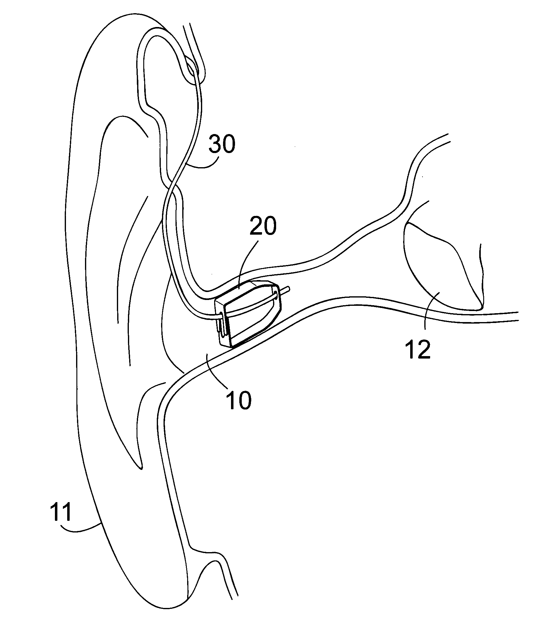
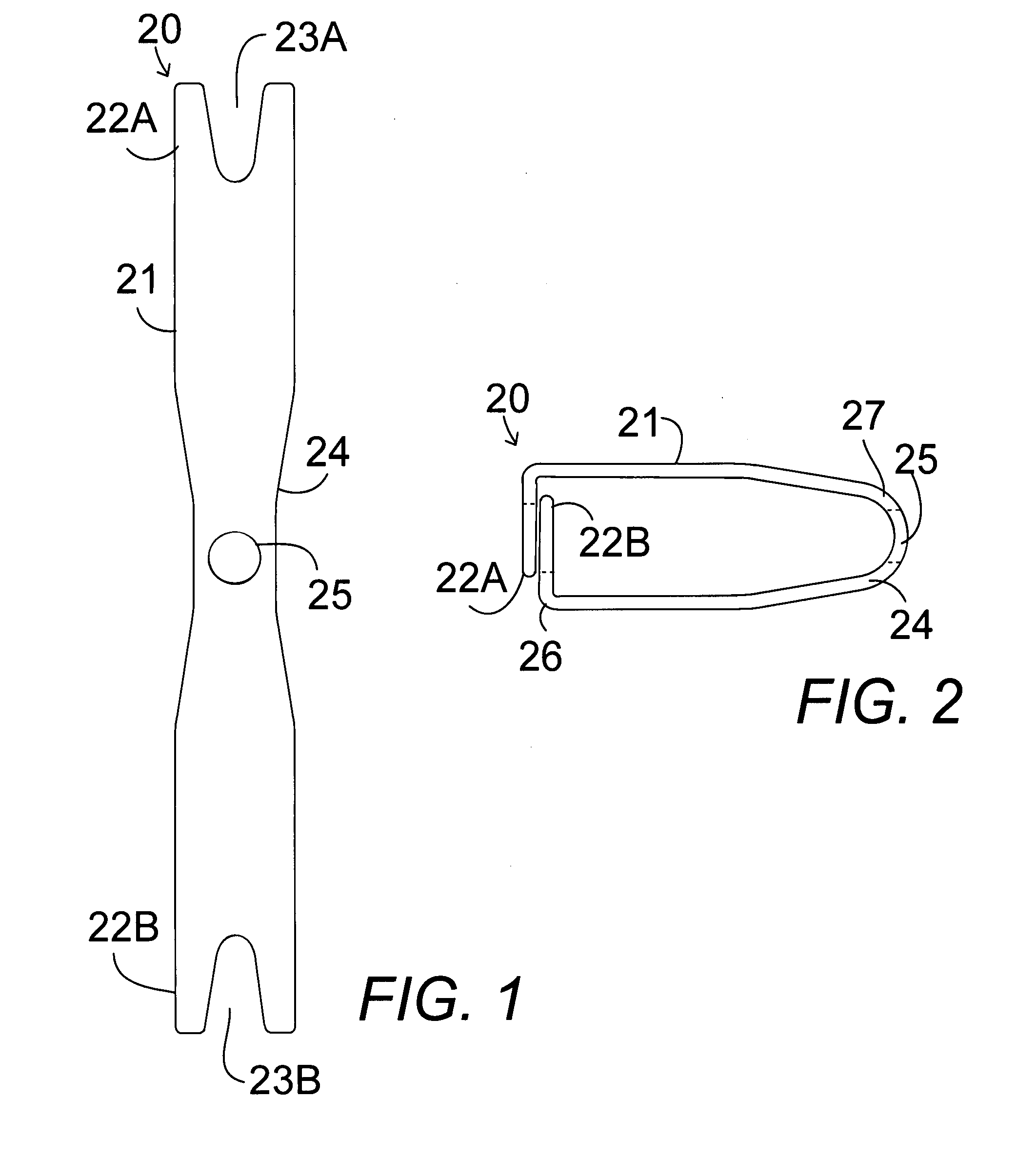
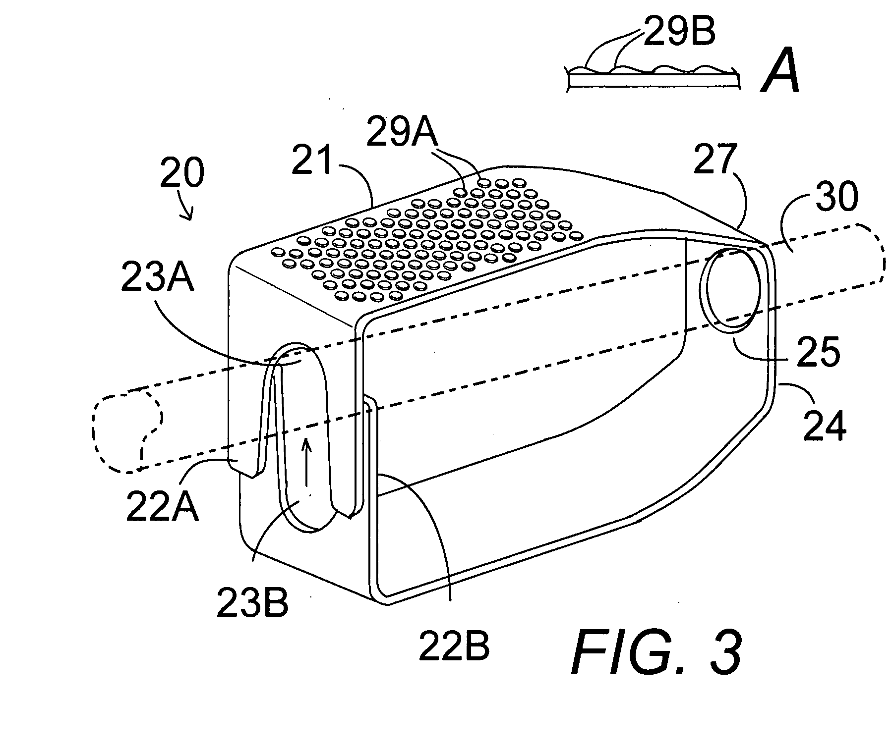
[0042]In FIGS. 1-4, an acoustic ear tube retainer spring device 20 comprises a U-shaped bent retainer spring body 21 with an end opening 25 and bent-over spaced pronged ends 22A and 22B with overlapping tapered end slots 23A and 23B to retain a 1 mm acoustic ear tube 30 in the external auditory meatus of the ear canal 10 of a user's ear 11 spaced apart from the ear drum 12, as shown in FIG. 4.

[0043]The retainer spring comprises an elongated strip of spring metal having substantially parallel side edges along the length of the elongated strip tapering to a narrow waist in a mid portion 24 having a center opening 25 through the mid portion to admit therethrough and retain therein the acoustic ear tube 30, and an open tapered slot 23A and 23B at each end of the elongated strip. The retainer spring bends into a U-shape for insertion into the ear canal of a user with the mid portion forming the curve 27 of the U-shape, which is inserted first. The parallel side portions contact the top a...


PUM


Abstract

A metal retainer spring bent into a U-shape retains an acoustic ear tube for use with behind-the-ear devices. The tube is held by a tube retaining opening in a tapered mid portion, forming the curved portion of the bent spring, and end slots bent together with the slots holding the tube. The retainer spring fits into the human ear canal for securing a narrow acoustic ear tube within a user's ear canal. The spring is manufactured from beryllium copper, or other material with excellent strength and great elasticity, and is then gold plated for the hypoallergenic properties. The top and bottom ear canal-contacting surfaces of each spring have a pebbled or rippled finish to limit slippage without causing abrasions.

Description

CROSS-REFERENCE TO RELATED APPLICATIONS[0001]Not Applicable.STATEMENT REGARDING FEDERALLY SPONSORED RESEARCH OR DEVELOPMENT[0002]Not Applicable.THE NAMES OF THE PARTIES TO A JOINT RESEARCH OR DEVELOPMENT[0003]Not Applicable.BACKGROUND OF THE INVENTION[0004]1. Field of the Invention[0005]The present invention relates to ear inserts for hearing aids, acoustic devices, and Bluetooth or hands-free cellular phones and particularly to a metal retainer spring for an acoustic hearing tube for use with behind-the-ear devices, wherein the retainer spring is adapted to fit into the human ear canal for securing a narrow acoustic ear tube device within a user's ear canal and the spring is manufactured from beryllium copper, or other material with excellent strength and great elasticity, and is then gold plated for the hypoallergenic properties, and the top and bottom ear canal-contacting surfaces of each spring have a pebbled or rippled finish to limit slippage without causing abrasions.[0006]2....

Claims


Application Information

Patent Timeline
Patent Type & Authority Applications(United States)
IPC IPC(8): H04R25/00
CPCH04R25/02
Inventor DAVIS, JOHN W.
Owner DAVIS JOHN W
Why Eureka
Try Eureka