Camera Cover

a technology for cameras and covers, applied in the field of cameras, can solve the problems of large restrictions on the aforementioned conventional technique, work difficulty, and out-of-focus vision, and achieve the effects of high mounting flexibility, excellent beauty, and high strength

Active Publication Date: 2009-02-12
AUTONETWORKS TECH LTD +2
View PDF10 Cites 22 Cited by
  • Summary
  • Abstract
  • Description
  • Claims
  • Application Information

AI Technical Summary

Benefits of technology

[0021]It is therefore an object of the present invention to provide a technique capable of mounting a focusing mechanism of a camera device on a vehicle without bringing the mechanism in contact with a work...

Problems solved by technology

Such work has to be conducted before mounting the shielding body 3, which makes the work difficult.
The contact with the adjuster may cause deviation from the original lens position, which results in out-of-focus vision.
Further, despite the fact that optical axis directions of the camera device body 1 may vary by vehicle type, so the mounting position of the camera device body 1 and the mounting position of the shielding body 3 vary ...

Method used


Image

  • Camera Cover
  • Camera Cover
  • Camera Cover

Examples


first preferred embodiment

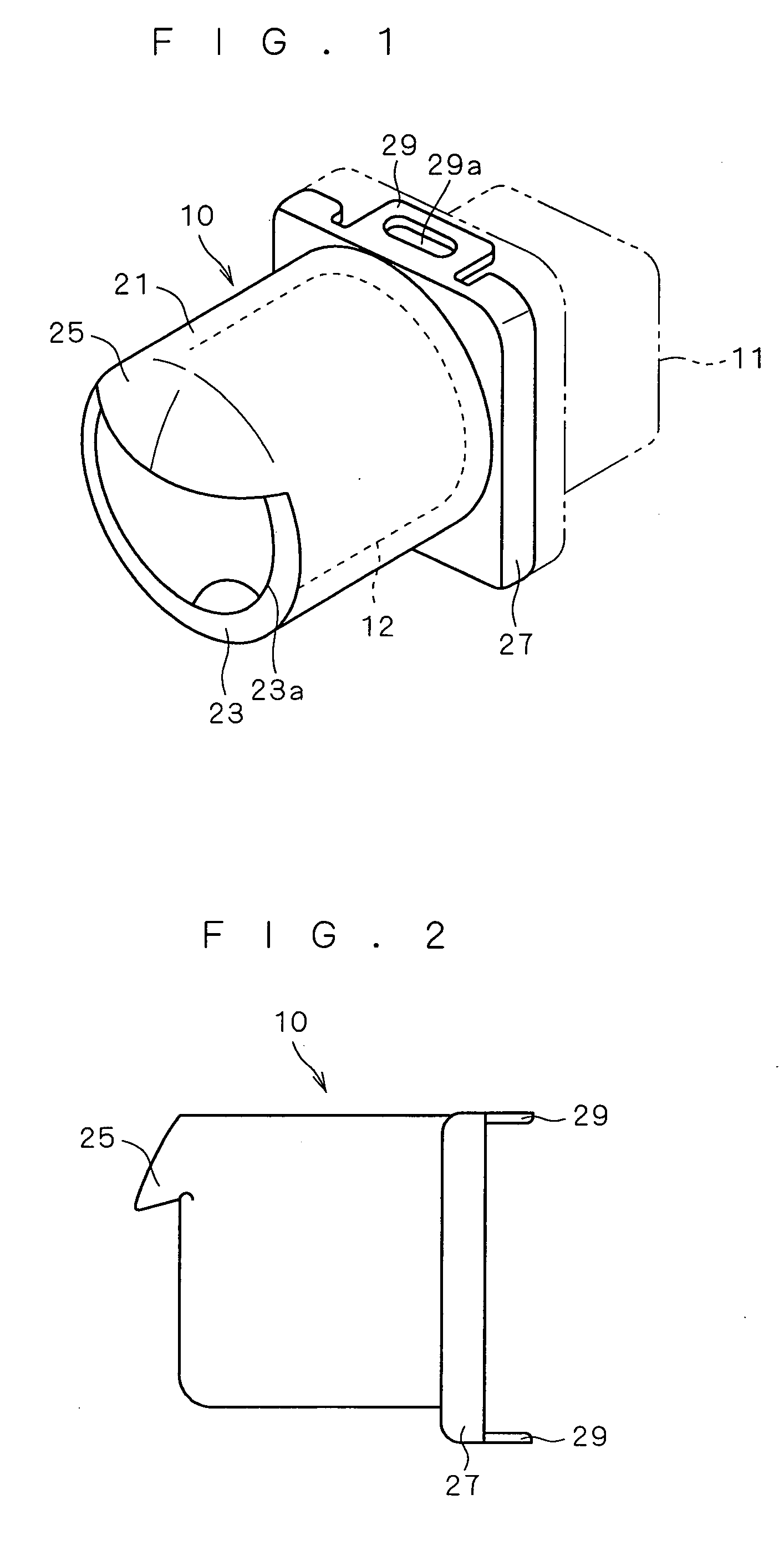
[0044]A description is given of a camera cover according to a first preferred embodiment of the present invention.

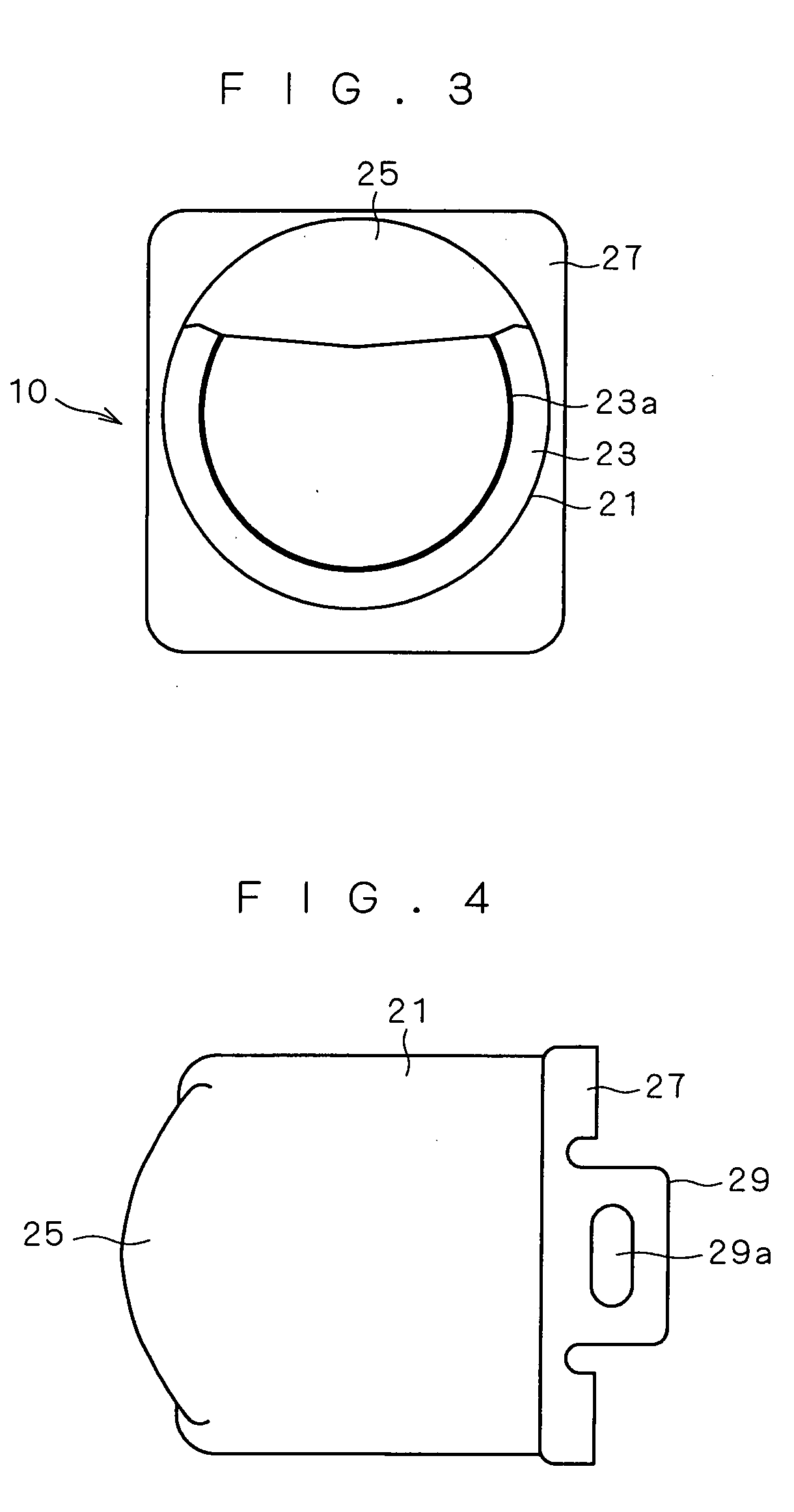
[0045]FIG. 1 is an appearance perspective view of a camera cover 10, FIG. 2 is a side view of the same, FIG. 3 is a front view of the same, and FIG. 4 is a plan view of the same.

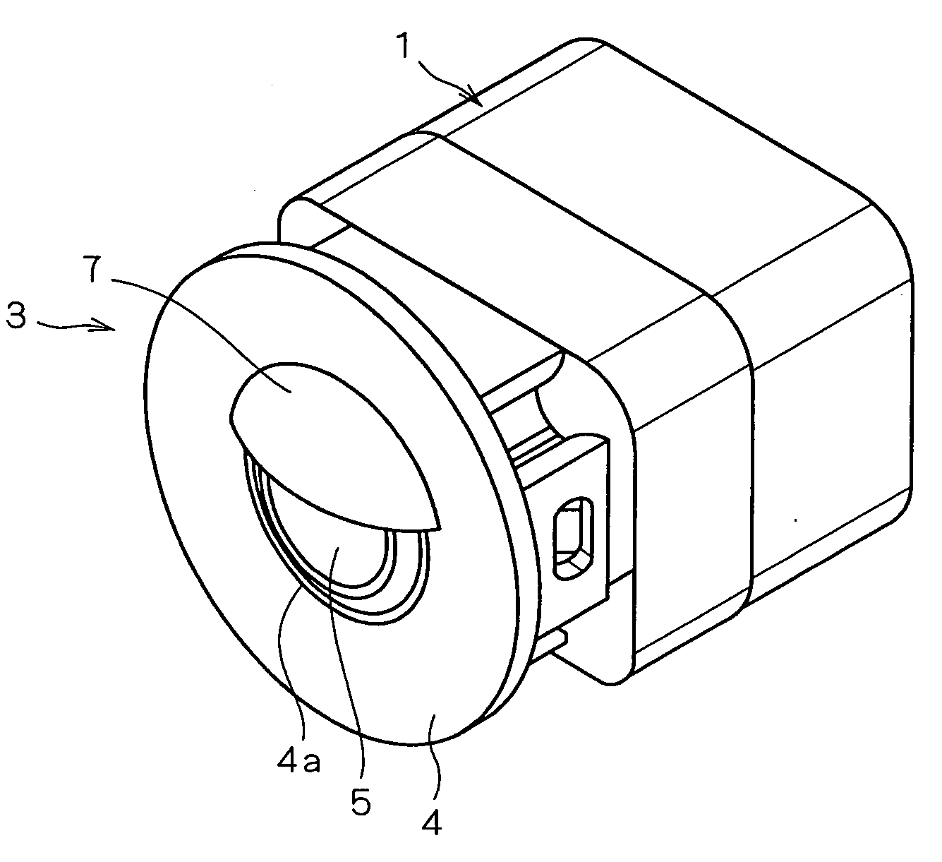
[0046]The camera cover 10 houses a camera device 12 that picks up images of scenery around a vehicle to protect the camera device 12, and is mounted on a bumper, a ventilation grille or the like of the vehicle.

[0047]The camera device 12 housed in the camera cover 10 includes a lens system, an image pickup device such as a CCD that picks up an image formed by the lens system, and a circuit substrate for driving the image pickup device.

[0048]The camera cover 10 is formed from prescribed industrial plastic, and includes a cylinder body 21 housing cylinder portions which are not shown of the lens system and a lens holder 13 (FIG. 5), a frame body 23 in ring shape integrally molded on an open frontal ...

second preferred embodiment

[0058]Next, a description is given of a camera cover according to a second preferred embodiment of the present invention.

[0059]FIG. 6 is an appearance perspective view of a camera cover 15, FIG. 7 is a side view of the same, FIG. 8 is a front view of the same, and FIG. 9 is a bottom view of the same.

[0060]In FIGS. 6 to 9, the elements having similar functions as those in the first preferred embodiment have the same reference numerals, and descriptions of those elements will be omitted.

[0061]This camera cover 15 is provided with the eyelid part 25 (first eyelid part) of the first preferred embodiment, and further with an eyelid part 26 (second eyelid part), for example.

[0062]The eyelid part 26 is arranged on the lower half of the frame body 23, and is formed to project toward the front to form a curved surface in a shape along the curved surface of the outer surface of the front lens of the lens system of the camera device 12, as illustrated in FIGS. 6, 7 and 8. The eyelid part 26 th...


PUM


Abstract

It is an object of the present invention to mount a focusing mechanism of a camera device on a vehicle without bringing the mechanism in contact with a worker's hands in an in-focus state of a lens system in the camera device having an eyelid part for preventing stray light covering part of a lens, and to improve the beauty and increase mounting flexibility. In a camera cover according to the present invention, a cylinder body (21) of the camera cover (10) covers most including the first half portion of the volume of the camera device, and the cylinder body (21), a frame body (23), an eyelid part (25) and/or an eyelid part (26), and a housing part (27) are integrally molded. Beauty seen from the front can be improved, and the beauty will not be spoiled when the camera device (12) is displaced together with the camera cover (10) and mounted.

Description

TECHNICAL FIELD[0001]The present invention relates to camera covers applied to camera devices mounted on vehicles.BACKGROUND ART[0002]There is a conventional technique of picking up an image of a dead angle of a vehicle by mounting a camera device such as a CCD camera on a bumper and the like of the vehicle, and displaying the picked up image on a display device inside the car.[0003]Now, light which enters from obliquely above a camera device is not just unnecessary, but causes stray light by being reflected in a lens or a camera case.[0004]To prevent such stray light, a shielding body 3 is disclosed as shown in FIGS. 10 and 11 that shields at least part of light from outside the image pickup visual field of a camera device body 1 mounted on a vehicle (e.g. patent documents 1 to 7).[0005]The shielding body 3 includes a plate-like body 4 in almost annular shape, and an eyelid part 7 formed over a round opening part 4a of the plate-like body 4 to cover the upper half of a lens outer s...

Claims


Application Information

Patent Timeline
IPC IPC(8): G03B17/02
CPCB60R11/04G03B17/02G03B11/04G03B11/045
Inventor YONEJI, OSAMU
Owner AUTONETWORKS TECH LTD
Why Eureka
Try Eureka