Chamfer drill

Inactive Publication Date: 2009-02-12
LIU HSU HSIU KWEI
View PDF4 Cites 9 Cited by
  • Summary
  • Abstract
  • Description
  • Claims
  • Application Information

AI Technical Summary

Benefits of technology

[0003]A primary object of the present invention is to provide an improved chamfer drill, which allows an operator to chamfer a drilled hole with reduced time and labor by turning a chamfer bit thereof rightward and leftward without the need of extracting the chamfer bit from the drilled hole each time the chamfer bit has been turned rightward.
[0004]Another object of the present invention is to provide an improved chamfer drill, which allows the use of only one handle for associating with differently sized chamfer bits, so that the chamfer drill may be produced at reduced cost and does not occupy a large storage space.

Problems solved by technology

Therefore, a lot of time and labor is consumed to complete the hole chamfering operation.
As a result, manufacturing and purchasing costs and storing space for the conventional chamfer drills are increased.

Method used


Image

  • Chamfer drill
  • Chamfer drill
  • Chamfer drill

Examples


Embodiment Construction

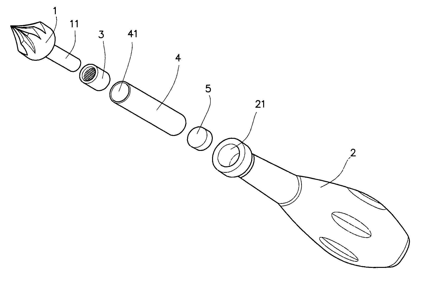
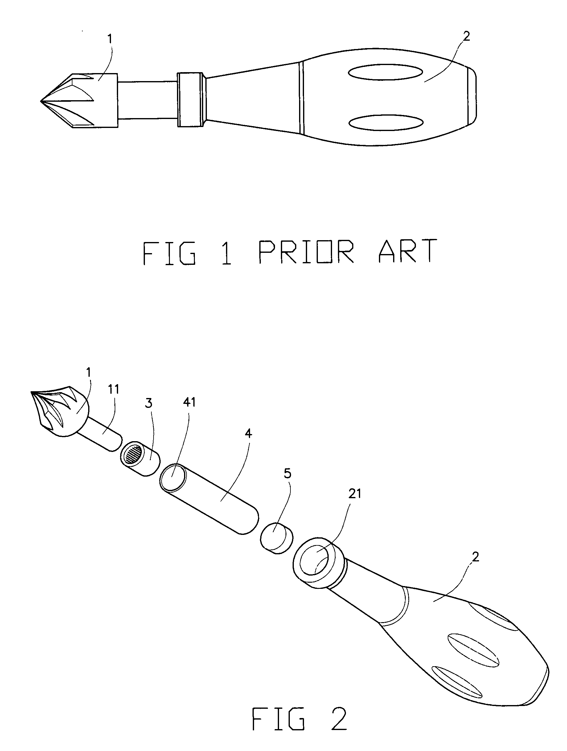
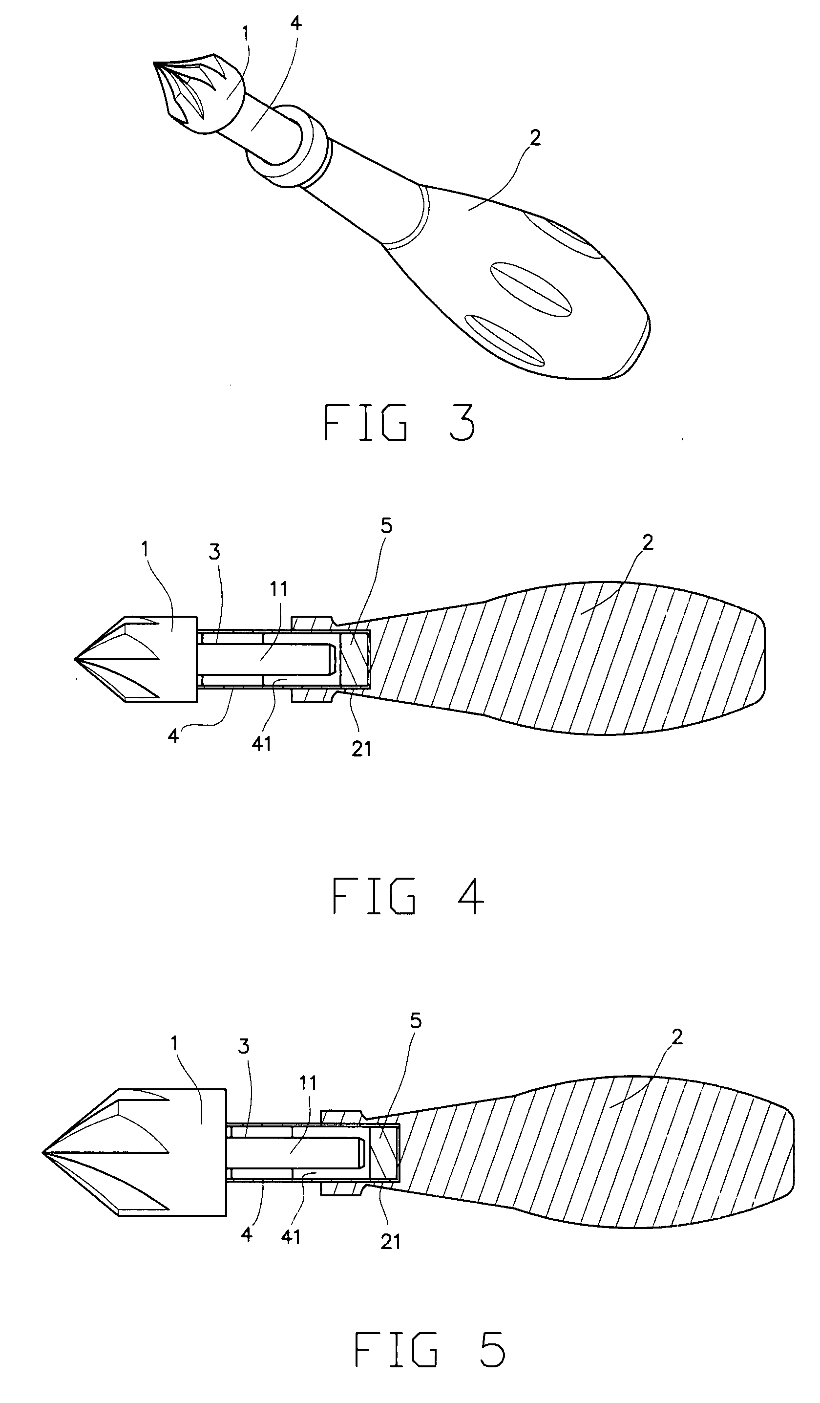
[0012]Please refer to FIGS. 2 and 3, which are exploded and assembled perspective views, respectively, of a chamfer drill according to the present invention. As shown, the chamfer drill of the present invention includes a chamfer bit 1, a handle 2, a unidirectional needle bearing 3, a sleeve 4, and a strong magnet 5.

[0013]The sleeve 4 defines a bore 41. The strong magnet 5 is fitted in the bore 41 to locate at a rear end of the sleeve 4. The bearing 3 is also fitted in the bore 41 to locate at a front neck portion of the sleeve 4. The sleeve 4 is connected to the handle 2 by fixedly fitting the rear end of the sleeve 4 in an axial bore 21 formed in a neck portion at a front end of the handle 2. The chamfer bit 1 has a rearward extended shaft 11, which is adapted to extend through a bore of the unidirectional needle bearing 3 to end at a position in the bore 41 of the sleeve 4 closely in front of the strong magnet 5, so that a rear end of the shaft 11 is magnetically firmly attracted...


PUM


Abstract

A chamfer drill includes a chamfer bit, a sleeve having a unidirectional needle bearing and a strong magnet respectively fitted in a front and a rear end thereof, and a handle associated at a front bore with the rear end of the sleeve. The chamfer bit has a rearward extended shaft, which is extended into the sleeve through the unidirectional needle bearing to end closely in front of the magnet, and is therefore magnetically attracted to the magnet and fixedly located in the sleeve. When the chamfer bit has been turned once to chamfer a drilled hole, an operator can continue the chamfering simply by turning the chamfer bit reversely and then forward again without the need of extracting the chamber bit from the hole being chamfered. And, only one handle is needed for associating with differently sized chamfer bits.

Description

FIELD OF THE INVENTION[0001]The present invention relates to a chamfer drill, and more particularly to a chamfer drill that can be operated with reduced time and labor, and manufactured at reduced cost.BACKGROUND OF THE INVENTION[0002]FIG. 1 shows a conventional chamfer drill used to chamfer a drilled hole. As shown, the conventional chamfer drill includes a chamfer bit 1 fixedly associated with a handle 2 to form an integral body. To use the chamfer drill with this structure to chamfer a drilled hole, first turn the handle 2 and drive the chamfer bit 1 into the drilled hole, and then extract the chamfer bit 1 before turning the handle 2 to drive the chamfer bit 1 into the drilled hole again. The turning and driving and the extracting of the chamfer drill into and from the drilled hole must be repeated until the drilled hole is satisfactorily chamfered. Therefore, a lot of time and labor is consumed to complete the hole chamfering operation. Moreover, since the chamfer bit 1 is fixe...

Claims


Application Information

Patent Timeline
IPC IPC(8): B23B51/10
CPCY10T408/9065B23B51/101
Inventor LIU, HSU HSIU-KWEI
Owner LIU HSU HSIU KWEI
Why Eureka
Try Eureka