Composite cutting inserts and methods of making the same

a composite material and cutting insert technology, applied in the direction of shaping cutters, manufacturing tools, presses, etc., can solve the problems of high cost of fabricating cutting inserts fabricated from monolithic carbide constructions using the higher grades of cemented carbides, difficult to optimize the composition of conventional monolithic indexable cutting inserts comprising a single grade of carbide material, and the difficulty of manufacturing composite carbide cutting inserts

Active Publication Date: 2009-02-12
KENNAMETAL INC
View PDF101 Cites 48 Cited by
  • Summary
  • Abstract
  • Description
  • Claims
  • Application Information

AI Technical Summary

Benefits of technology

[0012]Embodiments of the present invention include a method of producing a composite article, comprising introducing a first powdered metal grade from a feed shoe into a first portion of a cavity in a die and a second powdered metal grade from the feed shoe into a second portion of the cavity, wherein the first powder metal grade differs from the second powdered metal grade in chemical composition or particle size. The first powdered metal and the second powdered metal may be consolidated to form a compact. In various embodiments, the metal powders are directly fed into the die cavity. Also, in many embodiments, the method of the present invention allows substantially simultaneous introduction of the two or more metal powders into the die cavity or other mold cavity.

Problems solved by technology

However, cutting inserts fabricated from a monolithic carbide construction using the higher grades of cemented carbides are expensive to fabricate, primarily due to the high material costs.
In addition, it is difficult to optimize the composition of the conventional monolithic indexable cutting inserts comprising a single grade of carbide material to meet the different demands of each location in the insert.
At this time, composite carbide cutting inserts are more difficult to manufacture than rotary cutting tools.
However, the slurry-based method can only be applicable to indexable cutting inserts without chip breaker geometry or the chip breaker with very simple geometry.
This is because a thick layer of slurry will obviously alter the chip breaker geometry, in particular widely used indexable cutting inserts have intricate chip breaker geometry required to meet the ever-increasing demands for machining a variety of work materials.
As such, inserts in rotary cutting tools comprising a monolithic construction are inherently limited in their performance and range of applications.
Drilling inserts and other rotary tools having a monolithic construction will, therefore, not experience uniform wear and / or chipping and cracking at different points ranging from the center to the outside edge of the tool's cutting surface.
Therefore, the chisel edge of conventional drilling inserts of monolithic construction used in that application will wear at a much faster rate than the remainder of the cutting edge, resulting in a relatively short service life.
In both instances, because of the monolithic construction of conventional cemented carbide drilling inserts, frequent tool changes result in excessive downtime for the machine tool that is being used.

Method used


Image

  • Composite cutting inserts and methods of making the same
  • Composite cutting inserts and methods of making the same
  • Composite cutting inserts and methods of making the same

Examples


Embodiment Construction

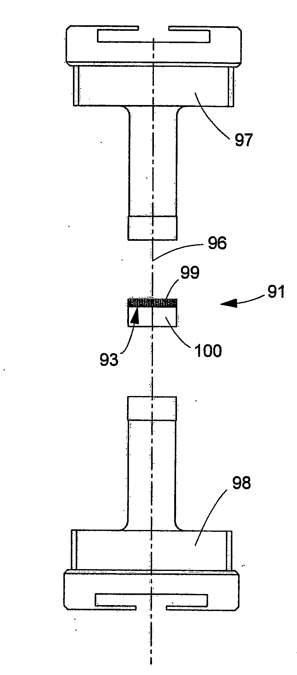
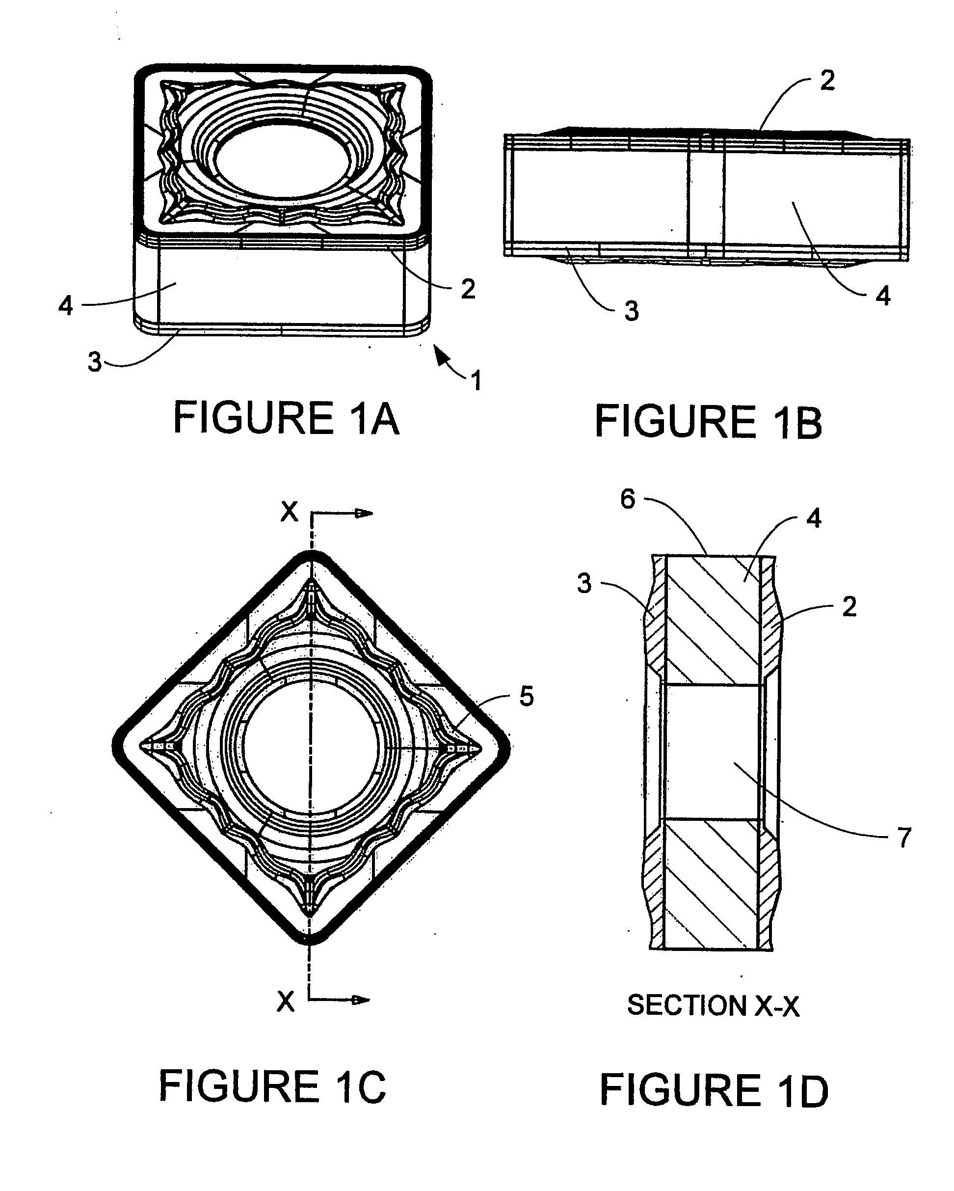
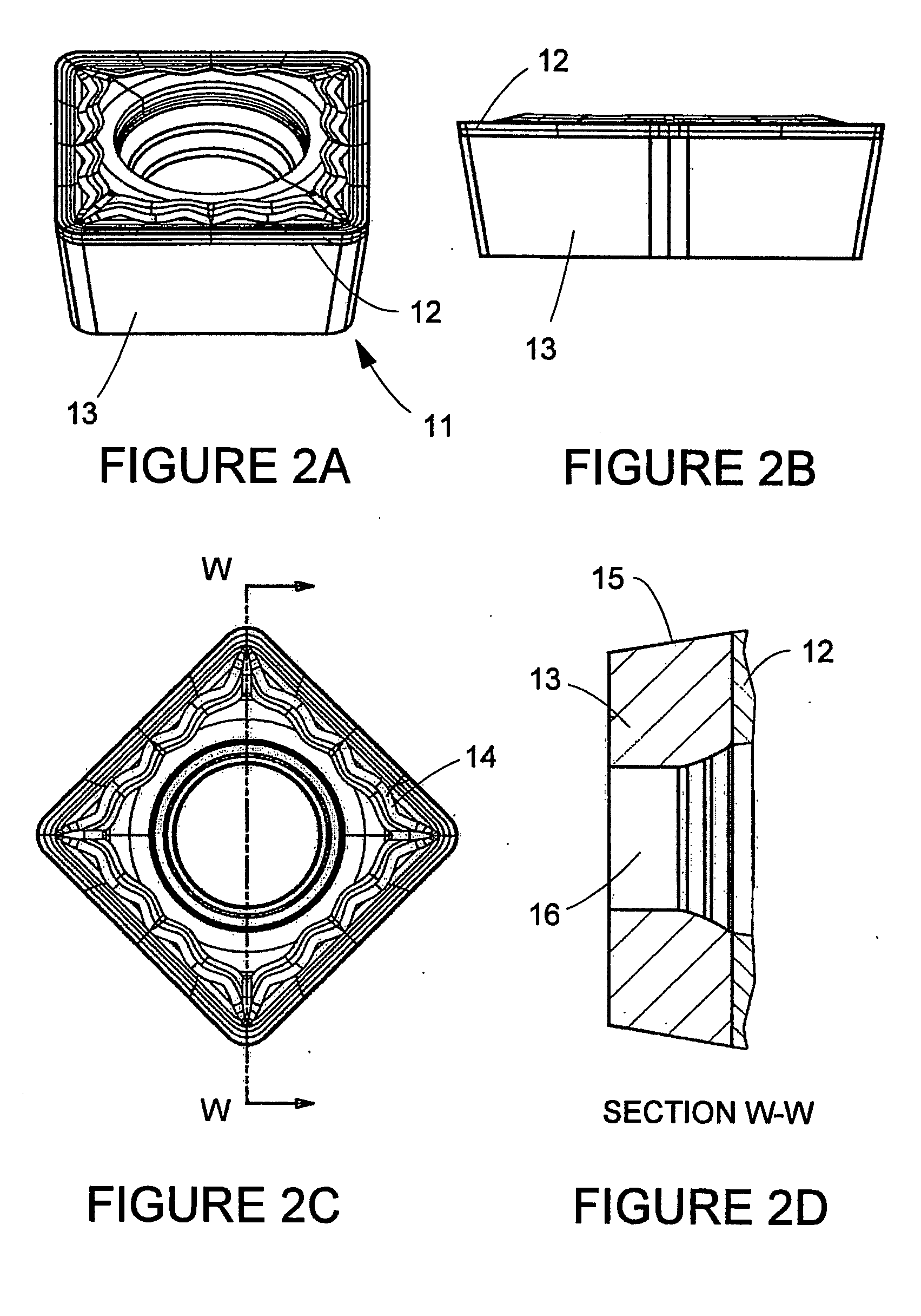
[0052]The present invention provides composite articles, such as cutting inserts, rotary cutting inserts, drilling inserts, milling inserts, spade drills, spade drill inserts, ballnose inserts and method of making such composite articles. The composite articles, specifically composite inserts, may further comprise chip forming geometries on either the top or bottom surfaces, or on both the top and bottom surfaces. The chip forming geometry of the composite article may be a complex chip forming geometry. Complex chip forming geometry may be any geometry that has various configurations on the tool rake face, such as lumps, bumps, ridges, grooves, lands, backwalls, or combinations of such features.

[0053]As used herein, “composite article” or “composite insert” refers to an article or insert having discrete regions differing in physical properties, chemical properties, chemical composition and / or microstructure. These regions do not include mere coatings applied to an article or insert....


PUM

PropertyMeasurementUnit
weight percentaaaaaaaaaa

Abstract

Embodiments of the present invention include methods of producing a composite article. A method comprises introducing a first powdered metal grade from a feed shoe into a first portion of a cavity in a die and a second powdered metal grade from the feed shoe into a second portion of the cavity, wherein the first powder metal grade differs from the second powdered metal grade in chemical composition or particle size. Further methods are also provided. Embodiments of the present invention also comprise composite inserts for material removal operations. The composite inserts may comprise a first region and a second region, wherein the first region comprises a first composite material and the second region comprises a second composite material.

Description

CROSS-REFERENCE TO RELATED APPLICATION[0001]This application is a divisional application of prior application Ser. No. 11 / 206,368, filed Aug. 18, 2005.TECHNICAL FIELD AND INDUSTRIAL APPLICABILITY OF THE INVENTION[0002]The present invention is generally directed to methods of making composite articles, such as tool blanks, cutting inserts, spade drill inserts, and ballnose endmills, having a composite construction including regions of differing characteristics or properties. The method of the present invention finds general application in the production of cutting tools and may be applied in, for example, the production of cemented carbide rotary tools used in material removal operations such as turning, milling, threading, grooving, drilling, reaming, countersinking, counterboring, and end milling. The cutting inserts of the present invention may be made of two similar cemented carbide materials but different grades.BACKGROUND OF THE INVENTION[0003]Cutting inserts employed for metal...

Claims


Application Information

Patent Timeline
Patent Type & Authority Applications(United States)
IPC IPC(8): B22F3/02B22F7/02
CPCB22F7/062Y10T428/252C22C29/00C22C29/08B22F2998/00Y10T428/24983Y10T428/12576Y10T428/12611Y10T407/27Y10T428/30Y10T428/12806Y10T428/12812Y10T428/12771Y10T428/24942B22F2207/01B22F2207/11B22F2207/13Y10T428/31678B30B15/304B30B15/306B22F7/06B23P15/28B22F7/00
Inventor FANG, X. DANIELWILLS, DAVID J.MIRCHANDANI, PRAKASH K.
Owner KENNAMETAL INC
Why Eureka
Try Eureka