Scintillating substance and scintillating wave-guide element

a scintillating waveguide and substance technology, applied in the direction of fluorescence/phosphorescence, optical radiation measurement, instruments, etc., can solve the problems of increasing the cost of manufacturing elements of size 2 mm, reducing the light output of luminescence and of effective atomic number, and the known scintillating material is a big scattering of the most important scintillating parameters, etc., to achieve the effect of increasing the reproducibility of properties, reducing the time and increasing the light outpu

Inactive Publication Date: 2001-08-21
SOUTHBOURNE INVESTMENTS
View PDF11 Cites 120 Cited by
  • Summary
  • Abstract
  • Description
  • Claims
  • Application Information

AI Technical Summary

Benefits of technology

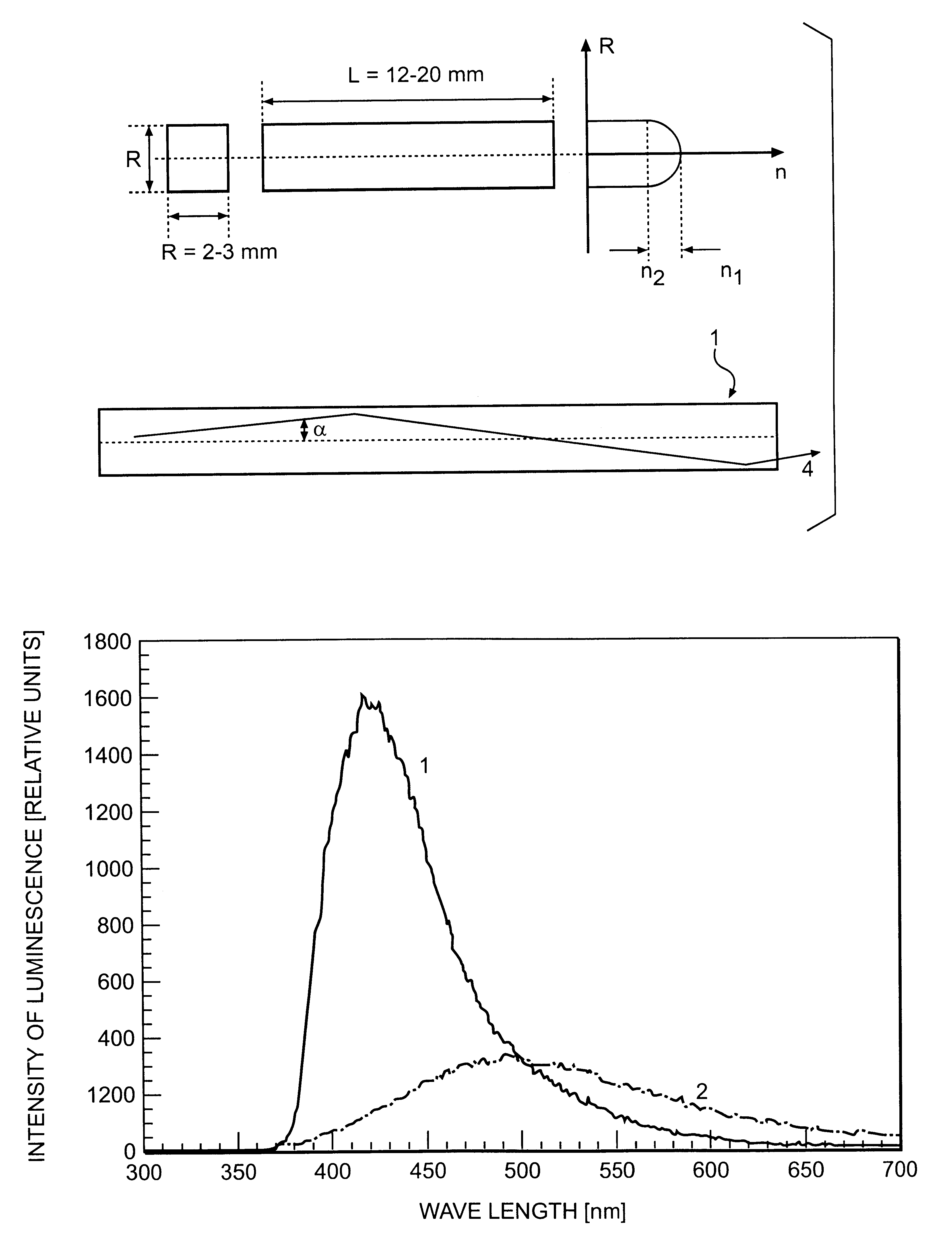
The technical task of the invention is the increase of the light output of luminescence, decrease of the time of luminescence of ions Ce.sup.3+, increase of the reproducibility of properties of grown single crystals, decrease of the cost of source melting stock for growing crystals scintillators, contained in great amount of Lu.sub.2 O.sub.3, the extension of the arsenal of technical facilities, implementing scintillating properties, the increase of effectiveness of the introduction

Problems solved by technology

The drawback of the known scintillating material is a big scattering of the most important scintillating parameters:
The drawbacks of the prototype are the decrease of the light output of luminescence and of effective atomic number, compared to known crystals of lutetium oxyorthosilicate.
One more essential drawback of crystals with a spatial group P2.sub.1 /c is a strong cracking during crystal boule cutting and their polishing, which sharply increase the cost of manufacturing elements of the size 2 mm.times.2 mm.times.15 mm for three dime

Method used


Image

  • Scintillating substance and scintillating wave-guide element
  • Scintillating substance and scintillating wave-guide element
  • Scintillating substance and scintillating wave-guide element

Examples


example 2

Obtaining a scintillation material on the basis of oxyortho silicate crystal, including cerium Ce, the composition of which is expressed by the chemical formula A.sub.2-x Ce.sub.x SiO.sub.5, wherein A is at least one element of the group Lu, Gd, Sc, Y, La, Pr, Nd, Sm, Eu, Th, Dy, Ho, Er, Tm, Yb, as well it contains fluorine F and / or at lest one of the elements of the group H, Li, Be, B, C, N, Na, Mg, Al, P, S, Cl, K, Ca, Ti, V, Cr, Mn, Fe, Co, Ni, Cu, Zn, Ga, Ge, As, Se, Rb, Sr, Zr, Nb, Mo, Ru, Rh, Pd, Ag, Cd, In, Sn, Sb, Cs, Ba, Hf; Ta, W, Re, Os, fr, Pt, Au, Hg, Tl, Pb, Bi, U, Th.

The data of table 2 demonstrate the possibility of using reagent Lu.sub.2 O.sub.3 with the purity of 99.8% instead of a more expensive Lu.sub.2 O.sub.3 with the purity of 99.995%. The introduction of additional compensating ions while using reagent Lu.sub.2 O.sub.3 with the purity of 99.8% eliminates the possibility of deterioration of the most important parameter--the constant of time of scintillations d...

example 3

Scintillating material based on the crystal of orthosilicate additional containing oxygen vacancies. For creating oxygen vacancies in crystalline samples, obtained by the method of Czochralski, their heating in vacuum during 2 hours at the temperature in the interval of 1200.degree. C.-1620.degree. was used.

The formation of oxygen vacancies insignificantly affects the scintillation parameters of crystals, grown from reagents with the purity of 99.995%. On the contrary, oxygen vacancies bring about the decrease by 20% -70% of the light output of crystals, additionally doped, for example, by ions of Mo, W, Ta, due to the formation of dying centres.

The presence of oxygen vacancies completely suppresses the luminescence of admixture rare earth ions Pr, Sm, Tb, Ho, Er, Tm, and does not affect the luminescence properties of ions of Ce.sup.3+. In crystals of oxyorthosilicate additionally containing oxygen vacancies completely suppressed and absent is the luminescence of ions of Tm.sup.3+ a...

example 4

Scintillating material on the basis of oxyorthosilicate crystal, which contains Ce.sup.3+ ions in the quantity of 5.times.10.sup.-5 f., units up to 0.1 f. units. For growing by Czochralski method of lutetium--cerium--tantalum orthosilicate crystal, containing Ce.sup.3+ ions in the range of 5.times.10.sup.-5 f. units, the melting stock was used with the chemical composition of Lu.sub.1.975 Ce.sub.0.0025 Ta.sub.0.005 SiO.sub.5.002 on the basis of source reagents (Lu.sub.2 O.sub.3, CeO.sub.2, Sio.sub.2, Ta.sub.2 O.sub.5) with the purity of 99.995%. The crystal was grown out of the iridium crucible with the diameter of 60 mm at a speed of pulling of 3 mm / hour and frequency of rotation of 20 rounds per minute.

At a contents of Ce.sup.3+ in a crystal in the amount of less than 5.times.10.sup.-5 f. units, the effectiveness of the scintillation luminescence of Ce.sup.3+ becomes insignificant due to a small concentration, as a result of which the light output (table 2) does not exceed 6% for ...


PUM


Abstract

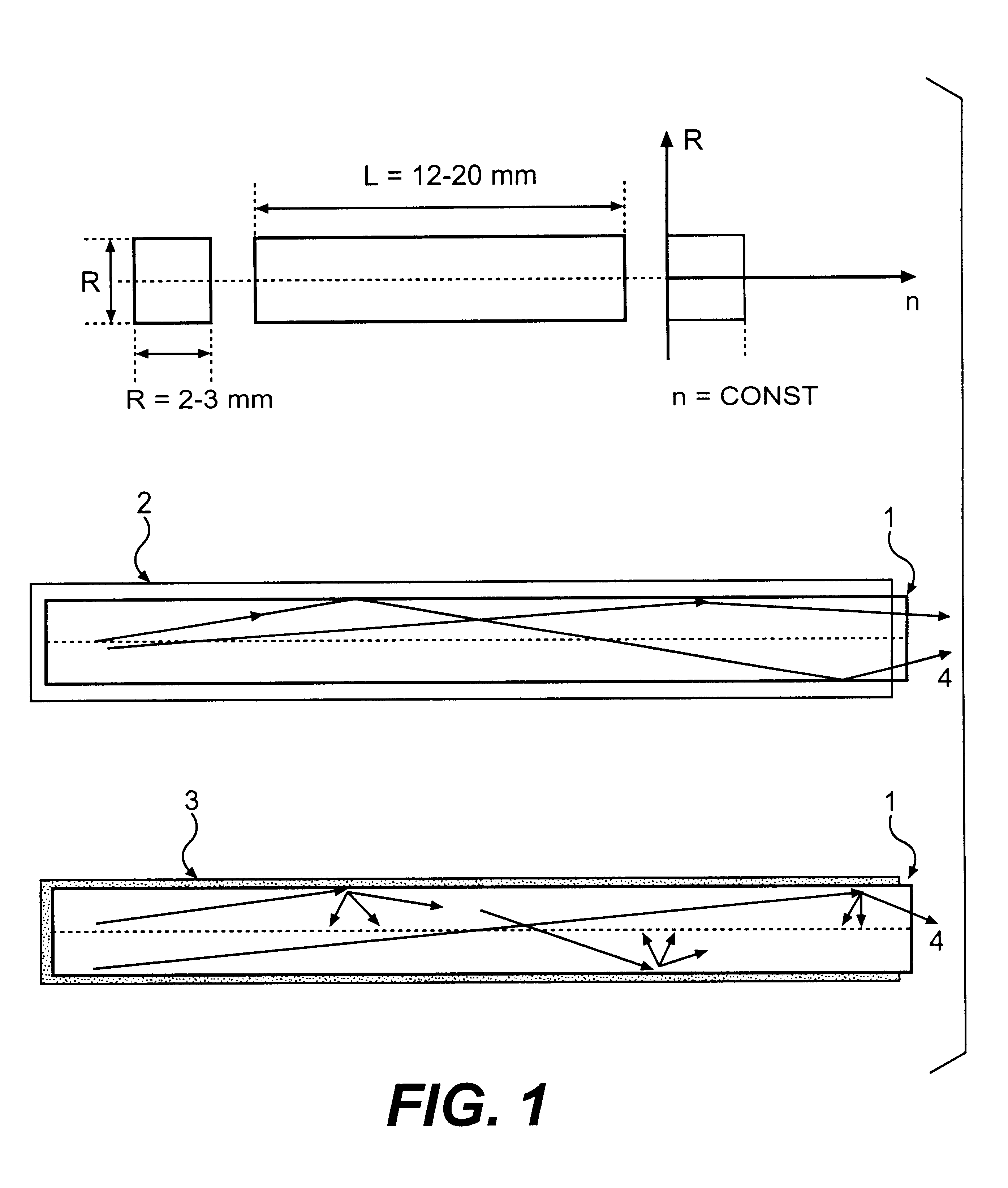
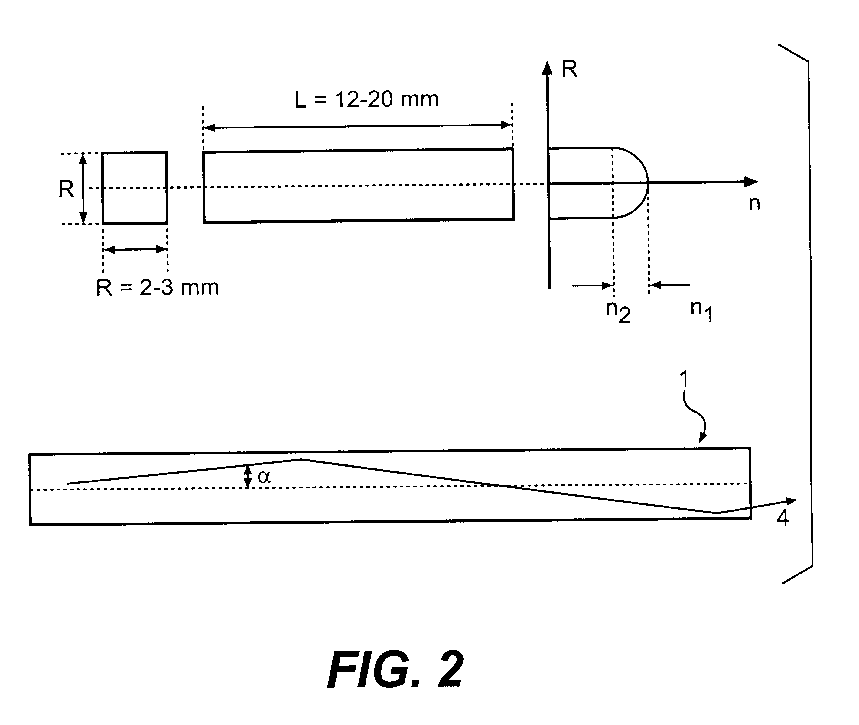
The invention is related to nuclear physics, medicine and oil industry, namely to the measurement of x-ray, gamma and alpha radiation; control for trans uranium nuclides in the habitat of a man; non destructive control for the structure of heavy bodies; three dimensional positron-electron computer tomography, etc.The essence of the invention is in additional ingredients in a chemical composition of a scintillating material based on crystals of oxyorthosilicates, including cerium Ce and crystallized in a structural type Lu2SiO5.The result of the invention is the increase of the light output of the luminescence, decrease of the time of luminescence of the ions Ce3+, increase of the reproducibility of grown crystals properties, decrease of the cost of the source melting stock for growing scintillator crystals, containing a large amount of Lu2O3, the raise of the effectiveness of the introduction of SCintillating crystal luminescent radiation into a glass waveguide fibre, prevention of cracking of crystals during the production of elements, creation of waveguide properties in scintillating elements, exclusion of expensive mechanical polishing of their lateral surface.

Description

The invention is related to nuclear physics, medicine and oil industry, namely to scintillating materials, and is meant for: registration and measurement of an x-ray, gamma and alpha radiation; control for trans uranium radio nuclides in the habitat of a man (in particular, in the zones of Chernobyl catastrophe); sparing (non-destructive) control of the structure of hard bodies; three dimensional positron-electron computer tomography and x-ray computer fluorography without the use of photo films; as well as for the control of the level of liquid in oil reservoirs.DESCRIPTION OF RELATED ARTKnown is the material of lutetium oxyorthosilicate with cerium LU.sub.2(1-x) Ce.sub.2x SiO.sub.5 where x is varying in the range from 2.times.10.sup.-4 to 3.times.10.sup.-2 (U.S. Pat. No. 4,958,080: date of Patent Sept. 18, 1990, "Lutetium orthosilicate single crystal Scintillator detector", Inventor C. I. Melcher, W. Redding Assignee: Schlumberger Technology Corp., as well as Victorov L. V., Skori...

Claims


Application Information

Patent Timeline
IPC IPC(8): C09K11/77G02B6/02C09K11/00C09K11/08C09K11/79C30B15/00G01T1/202C30B29/34G02B6/028
CPCC09K11/7774G02B6/02G02B6/0281C09K11/77742
Inventor ZAGUMENNYI, ALEXANDER IOSIFOVICHZAVARTSEV, YURY DMITRIEVICHSTUDENEKIN, PAVEL ALEKSEEVICH
Owner SOUTHBOURNE INVESTMENTS
Why Eureka
Try Eureka