Storage battery

Inactive Publication Date: 2009-02-12
HONDA MOTOR CO LTD
View PDF6 Cites 24 Cited by
  • Summary
  • Abstract
  • Description
  • Claims
  • Application Information

AI Technical Summary

Benefits of technology

[0011]The storage battery may further include an anchor portion formed in the lower end of the terminal, the anchor portion being embedded by a resin used for forming the lid, to generate an anchor effect.
[0012]Since each of the terminal portions formed by integrating the terminal, the bushing and the conductive portion together is embedded in the lid by insert molding, it is possible to not only omit the necessity to perform a a fixing work for fixing the terminal to the lid, but also reduce the number of parts or members, thereby providing a storage battery that is capable of enabling an easy and speedy fabrication work. In addition, since the lower portion of the bushing and the conductive portion are tightly embedded in the lid by insert molding, it is possible to prevent an electrolyte from being easily intruded from the storage battery into the lid located above through a gap between the bushing and the lid. Furthermore, even if the electrolyte is intruded into the upper side, a plurality of annular protrusions protruding outwards from the side wall of th

Problems solved by technology

This causes the fabrication process to be troublesome.
Furthermore, since the extension that connects the bushing to the terminal is exposed to the outside, an e

Method used


Image

  • Storage battery
  • Storage battery
  • Storage battery

Examples


Embodiment Construction

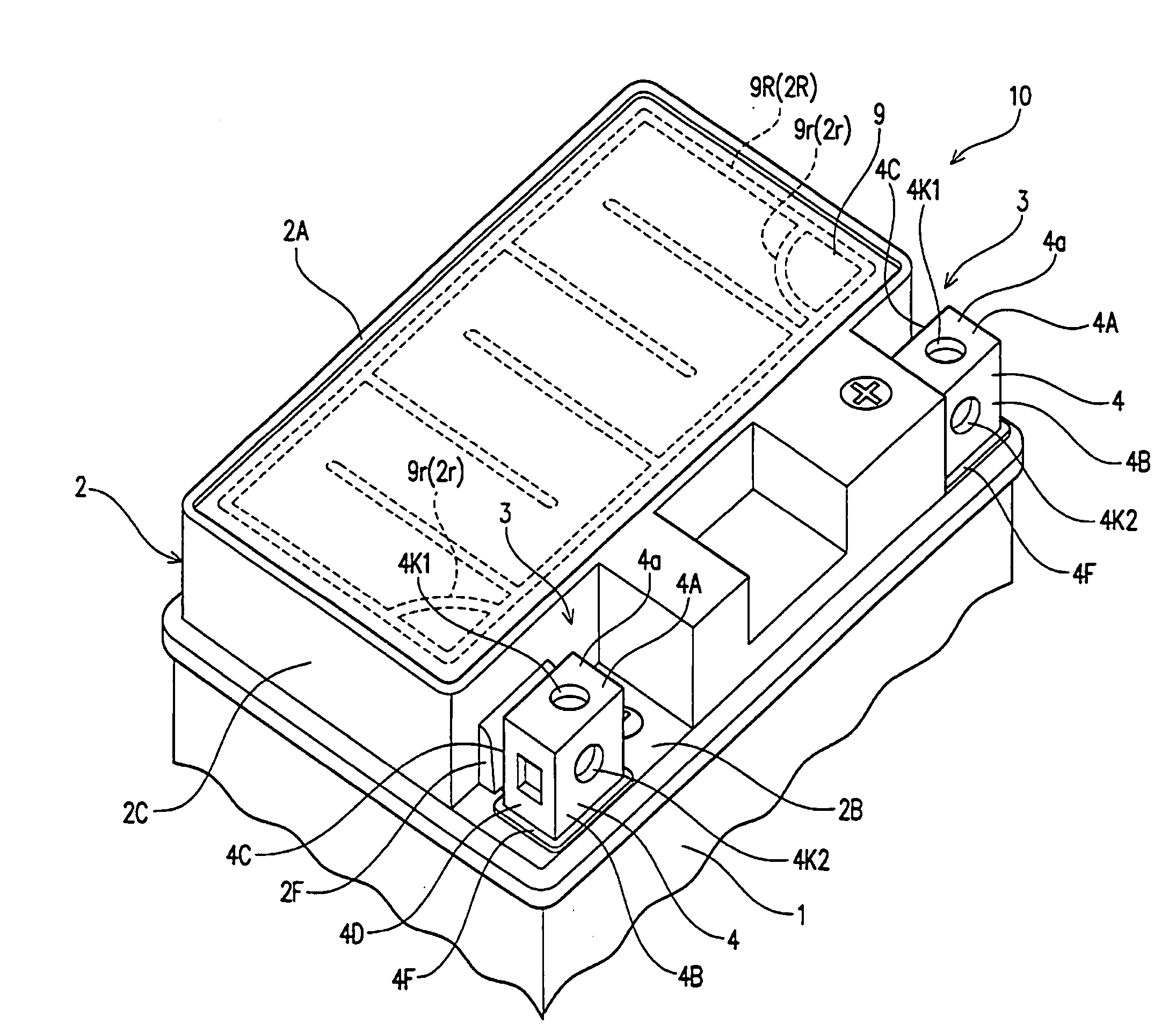
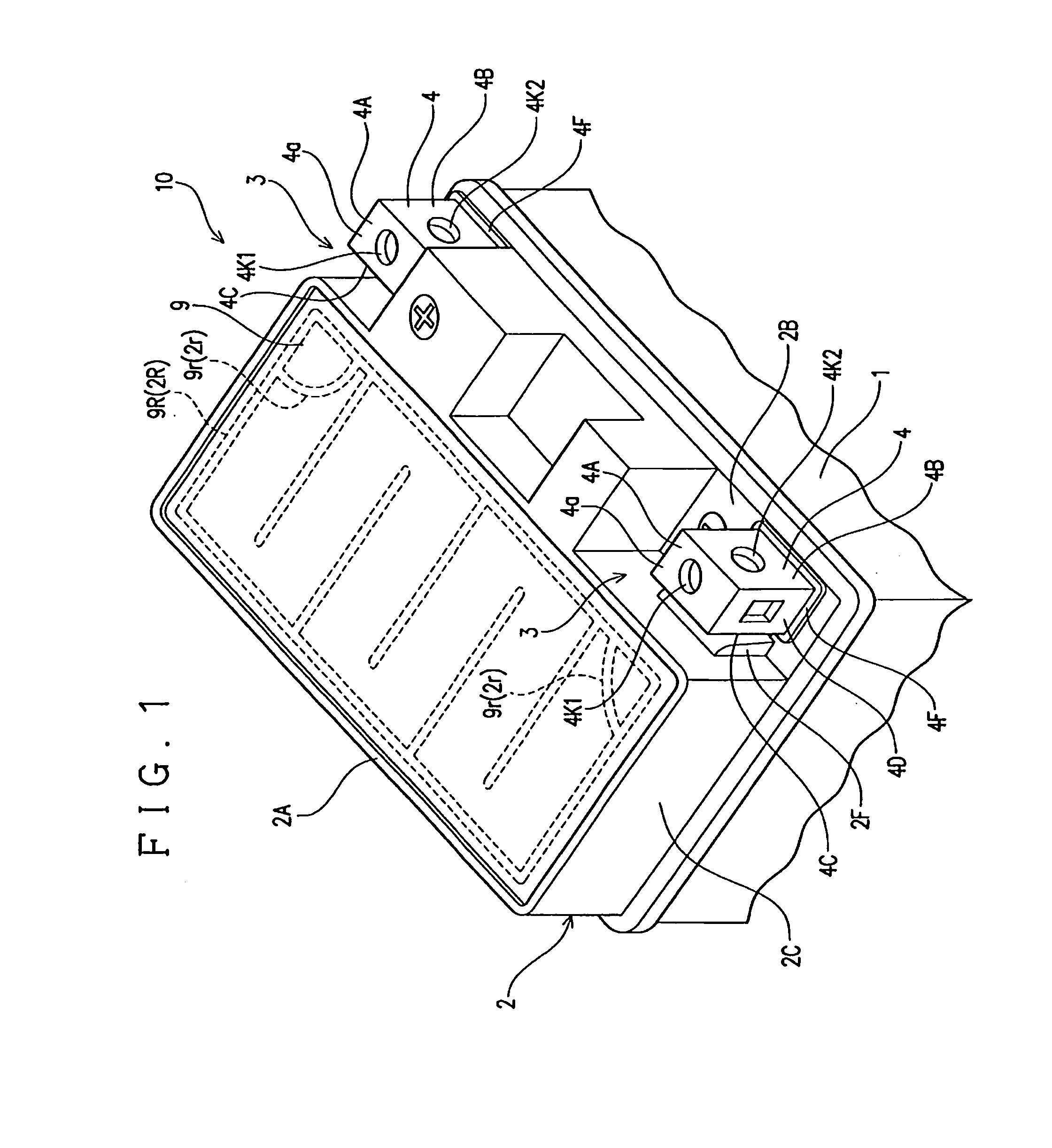
[0019]FIG. 1 shows a lead storage battery (hereinafter, simply referred to “storage battery”) especially suitable for a case that the storage battery is mounted on a motorcycle, but can be used for other purposes. This storage battery 10, includes a container 1 having a rectangular shape as seen in plan; a lid 2 made of a synthetic resin and having a rectangular shape as seen in plan for closing and opening of an upper end of the container 1; and an auxiliary lid 9 for closing an opening of an upper end of the lid 2.

[0020]Cutout portions 3 are formed respectively at two respective corners, which are oppositely located along either one long side of the lid 2, of four corners of the rectangular lid 2, and terminals 4 and 4 respectively forming a positive polarity and a negative polarity are disposed in the respective cutout portions 3 and 3 (the right terminal is designated as a positive terminal and the left terminal is designated as a negative terminal in this embodiment), thereby p...


PUM


Abstract

There is provided storage battery that is capable of enabling an easy and speedy fabrication work as well as preventing a terminal thereof from fading or decaying for a long time. A storage battery includes: a lid made of a synthetic resin for closing a container and having cutout portions or recesses; terminals disposed respectively in the cutout portions or the recesses; bushings each having a tubular shape located inside the lid; electrode poles extending from the container for taking out power, the electrode poles respectively inserted into the bushings and welded thereto; conductive portions each for electrically connecting an upper side of the bushing and a lower side of the terminal disposed in parallel with the bushing in a horizontal direction in each of the cutout portions or the recesses; and an auxiliary lid for covering the bushing disposed inside the lid from above. The terminal, the bushing and the conductive portion are monolithically molded to form a terminal portion of the corresponding terminal in each of the cutouts or the recesses. Annular protrusions protrude outwards from a side wall of the conductive portion. At least a lower portion of the bushing and the conductive portion of the terminal portion in each of the cutouts or the recesses are embedded in the lid by insert molding.

Description

CROSS REFERENCE TO RELATED APPLICATION[0001]This application claims priority from Japanese Patent Application No. 2007-204331, which are incorporated herein by reference.BACKGROUND OF THE INVENTION[0002]1. Field of the Invention[0003]The present invention relates to a storage battery suitable for a motorcycle, and more in particular, to a storage battery capable of downsizing by a configuration that a terminal for taking out power does not largely protrude upwards from a lid of a storage battery.[0004]2. Description of the Background Art[0005]A storage battery having a pair of terminals is configured as follows. In each terminal, a bushing having a tubular shape is disposed inside of a lid and an electrode pole protruding upwards from a container is inserted into the bushing to be welded. The terminal is disposed in a cutout portion formed on a front side in a horizontal direction from each bushing. The disposed terminal is connected to the bushing. This configures a vertically comp...

Claims


Application Information

Patent Timeline
IPC IPC(8): H01M2/02H01M50/147H01M50/531
CPCH01M2/043H01M2/307H01M2/26Y02E60/10H01M50/147H01M50/561H01M50/531
Inventor NAKAYAMA, YASUHIDEHOJO, EIJITAKAHASHI, SHUJI
Owner HONDA MOTOR CO LTD
Why Eureka
Try Eureka