Injection needle apparatus for making injection in tissue in body cavity

a technology of injection needle and tissue, which is applied in the field of injection needle apparatus, can solve the problems of difficult difficult to insert the needlepoint into the tissue region, and the needle body readily pierces the blood vessel, so as to facilitate the insertion and the tissue region. insertion, easy to catch the blood vessel, the effect of easy insertion

Inactive Publication Date: 2009-02-12
OLYMPUS CORP
View PDF8 Cites 13 Cited by
  • Summary
  • Abstract
  • Description
  • Claims
  • Application Information

AI Technical Summary

Benefits of technology

[0006]However, as shown in FIG. 11B, when the needle is to be inserted into the tissue region where the needlepoint points downward, the sharp needlepoint moves closer to the tissue region so that the needlepoint is apt to be caught on the outer surface of the tissue region and hence the needlepoint is easy to insert into the tissue region.
[0007]Moreover, as shown in FIG. 11A, when the needle is to be inserted into the blood vessel in the state where the needlepoint points upward, the oblique base portion of the needlepoint comes into contact with the blood vessel and the blood vessel moves away, thereby making it difficult to catch the blood vessel. As shown in FIG. 12A, when an angle between a tissue surface of the blood vessel and an axial direction of the needle is increased, the needlepoint easily catch the blood vessel. Therefore, the angle must be increased to make the insertion being easy. However, as shown in FIG. 12A, when the angle between the blood vessel and the axial direction of the needle is increased to make the insertion, a region where the needlepoint and the blood vessel are crossed becomes narrow to make it hard to catch the blood vessel, and to cause a problem that the needle body readily pierces the blood vessel after the needle body is inserted into the blood vessel.

Problems solved by technology

Further, the oblique base portion slides on the outer surface of the tissue region and the sharp needlepoint readily moves away from the tissue region, and hence the needlepoint is hard to insert into the tissue region.
Moreover, as shown in FIG. 11A, when the needle is to be inserted into the blood vessel in the state where the needlepoint points upward, the oblique base portion of the needlepoint comes into contact with the blood vessel and the blood vessel moves away, thereby making it difficult to catch the blood vessel.
However, as shown in FIG. 12A, when the angle between the blood vessel and the axial direction of the needle is increased to make the insertion, a region where the needlepoint and the blood vessel are crossed becomes narrow to make it hard to catch the blood vessel, and to cause a problem that the needle body readily pierces the blood vessel after the needle body is inserted into the blood vessel.

Method used


Image

  • Injection needle apparatus for making injection in tissue in body cavity
  • Injection needle apparatus for making injection in tissue in body cavity
  • Injection needle apparatus for making injection in tissue in body cavity

Examples


Embodiment Construction

[0038]Embodiments of the present invention will now be explained hereinafter with reference to the accompanying drawings.

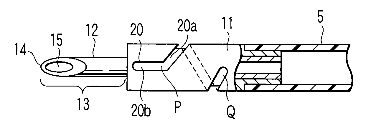
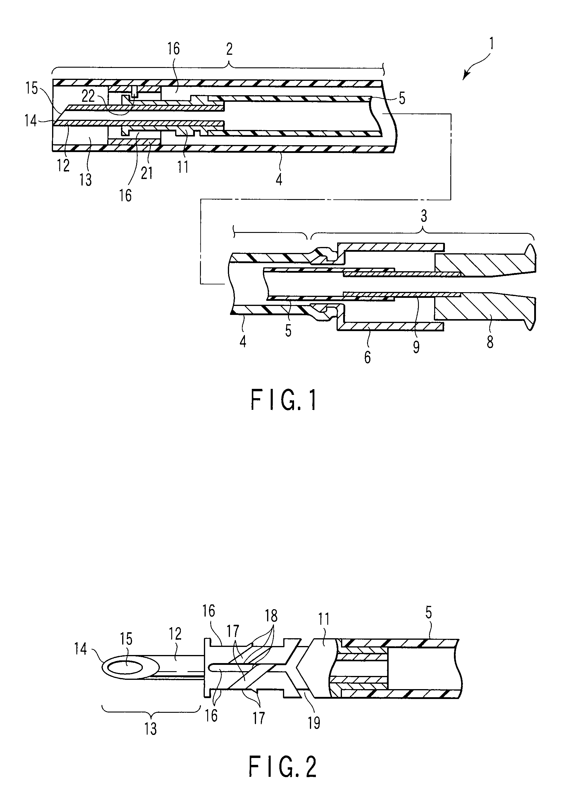
[0039]FIGS. 1 to 8 show an injection needle apparatus for an endoscope, according to one embodiment of the present invention. As shown in FIG. 1, an injection needle apparatus 1 for an endoscope is configured to be divided into an inserting portion 2 and an operating portion 3. The inserting portion 2 has a flexible outer tube (an outer sheath) 4 as an outer tube member and a flexible inner tube 5 configuring a part of an inner tube member, and the inner tube 5 is inserted into the outer tube 4 to be movable back and forth along a longitudinal axis direction of the inner tube 5. Both the outer tube 4 and the inner tube 5 have a relationship that they can relatively move in a central axis direction in a longitudinal direction of the inserting portion 2. The outer tube 4 and the inner tube 5 are formed of a resin having elasticity, e.g., fluoroplastic, polyethylene,...


PUM


Abstract

An injection needle apparatus in which an operation for relatively moving an outer tube 4 and an inner tube 5 is performed to project and retract a needle body 12 from and into a distal end of the outer tube 4, and to carry out a movement of rotation of the needle body 12 at a predetermined angle by relative forward and backward movements of the outer tube 4 and inner tube 5 in their longitudinal directions every time the forward and backward movement operations is repeated, thereby enabling changing a direction of a needlepoint 14 of the needle body 12 at each angle.

Description

TECHNICAL FIELD[0001]This invention relates to an injection needle apparatus that is preferably used with an endoscope and injects a liquid medicine, etc. into a tissue or a tissue region such as a blood vessel in a cavity of a living body.BACKGROUND ART[0002]It has been done that an injection needle is introduced into a body cavity through an instrument, such as a channel, of an endoscope and a liquid medicine is injected into a tissue region, such as an organ or a blood vessel, in a body cavity by the injection needle. This type of injection needle has a double sheath structure in which an inner tube having a distal end provided with an injection needle body is inserted in an outer sheath, as disclosed in JP-A 2001-58006 (KOKAI).[0003]When using this type of injection needle, the following procedure is carried out. First, a syringe filled with a liquid medicine is attached to a mouthpiece on a proximal end of the inner tube. Then, the outer sheath in this state is inserted into th...

Claims


Application Information

Patent Timeline
Patent Type & Authority Applications(United States)
IPC IPC(8): A61B1/018A61M5/32
CPCA61M25/0084A61B17/3478
Inventor FUJISAKI, KENMATSUNO, KIYOTAKA
Owner OLYMPUS CORP
Why Eureka
Try Eureka