Laser engraver

a laser engraving and laser technology, applied in welding apparatus, metal-working equipment, manufacturing tools, etc., can solve the problems of shortening the lifetime of laser engraving, easy damage or even penetration of glass tubes, and limited engraving speed and quality, so as to achieve optimal engraving

Inactive Publication Date: 2009-02-19
XINGYUN COMP
View PDF4 Cites 3 Cited by
  • Summary
  • Abstract
  • Description
  • Claims
  • Application Information

AI Technical Summary

Benefits of technology

[0007]An object of the present invention is to provide a laser engraver disposed with a modulation mechanism on an axis of output laser beam for adjusting the frequency of the output laser beam to achieve optimal engraving effect.

Problems solved by technology

First, continuous operation of strike voltage shortens the lifetime of laser and easily damages or even penetrates the glass tube.
Second, engraving speed and quality are limited by low modulation frequency.
Third, energy power of laser beam changes suddenly when direct-voltage modulation is used and the power of the laser beam is lower compared with constant level, so that the engraving level of deepness is affected.

Method used


Image

  • Laser engraver
  • Laser engraver
  • Laser engraver

Examples


Embodiment Construction

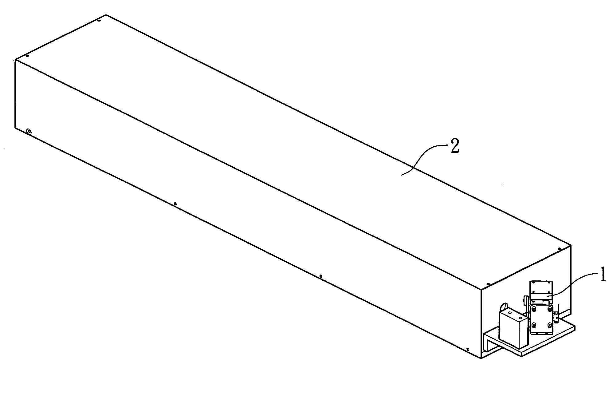
[0013]The present invention provides a laser engraver comprising a glass laser tube 2 and a modulation mechanism 1. The glass laser tube 2 is used for outputting laser beam utilized by the laser engraver. The modulation mechanism 1 is provided on the optical path of the output laser beam from the glass laser tube 2 and used for adjusting the frequency of the output laser beam

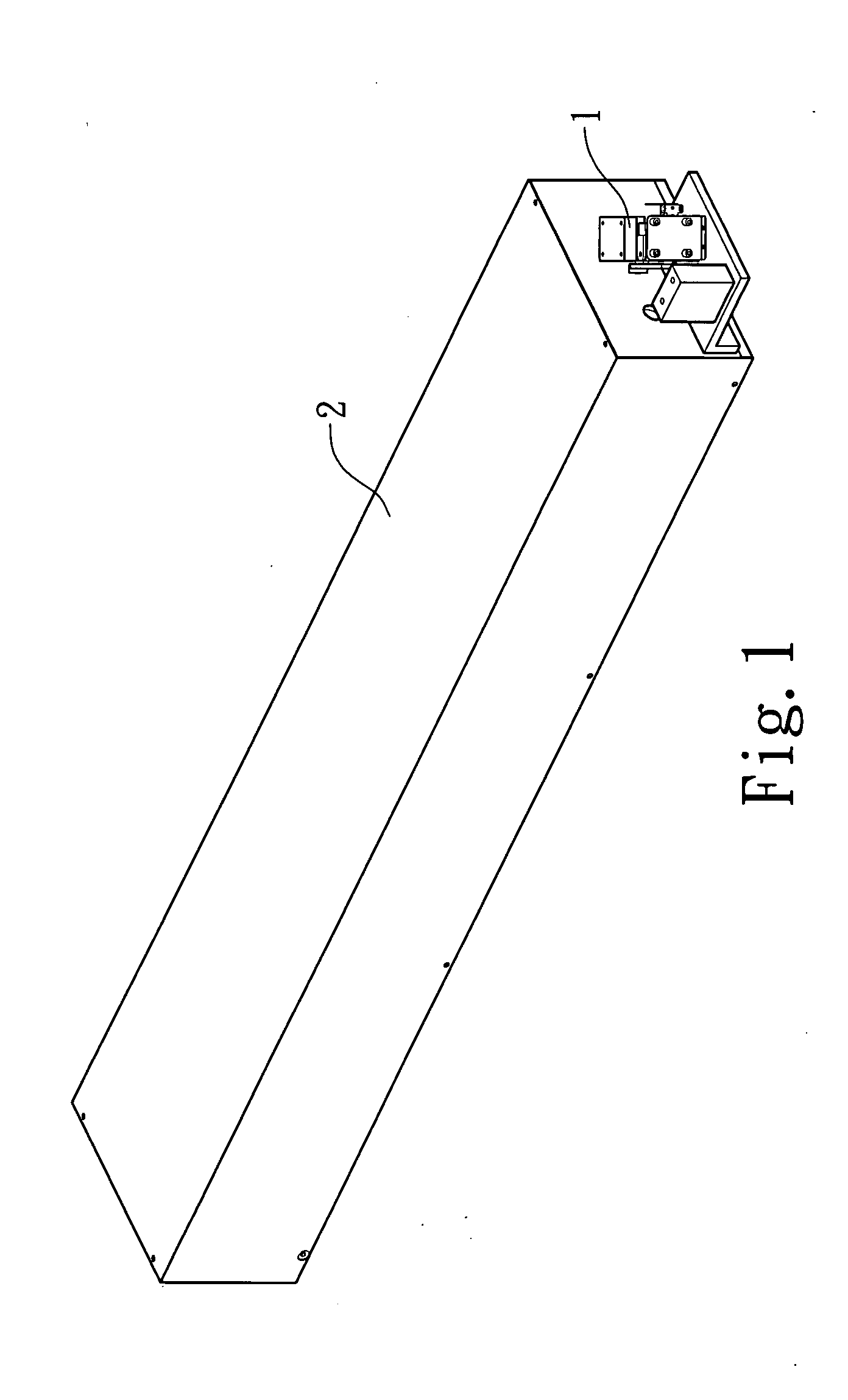
[0014]FIG. 1 is a perspective view of the present invention. In this embodiment, the modulation mechanism 1 is connected with one end of the glass laser tube 2 and disposed on the optical path of the output laser beam from the glass laser tube 2.

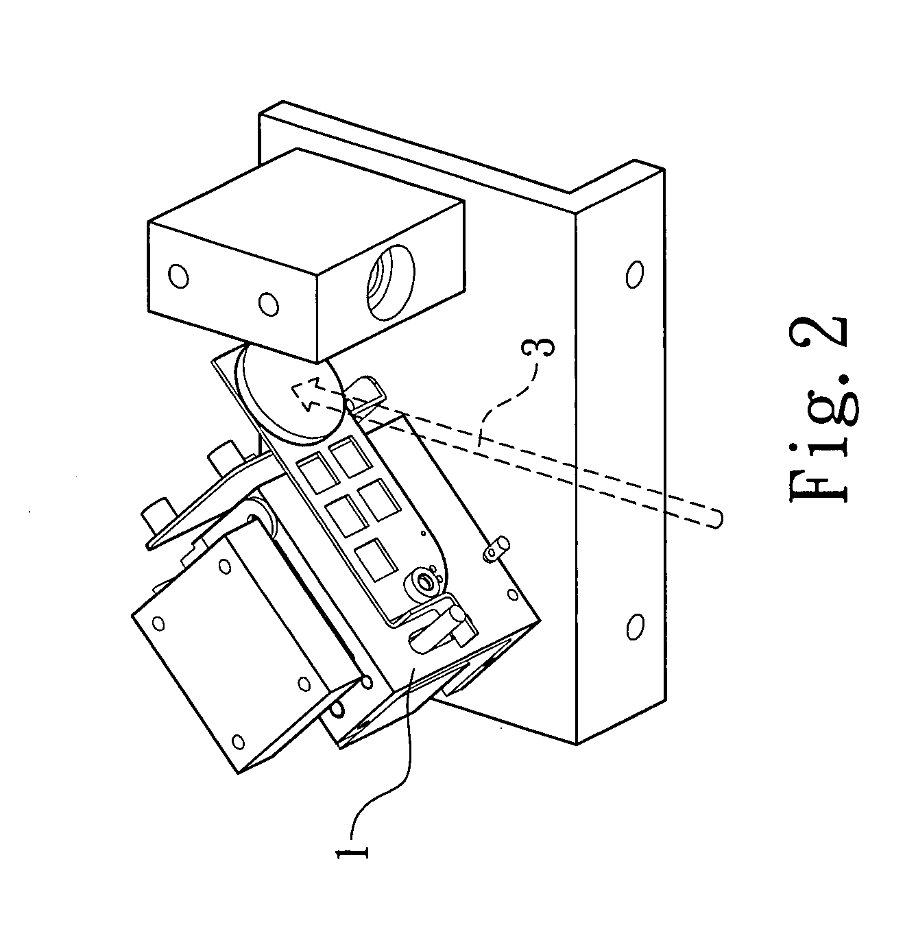
[0015]As shown in FIGS. 2-3, in practice, after the glass laser tube 2 is activated, the output laser beam 3 will pass through the modulation mechanism 1 and the frequency of the output laser beam 3 can be adjusted by the modulation mechanism 1. By means of the disposition of the modulation mechanism 1, the glass laser tube 2 can output laser beam continuously to maintai...


PUM

PropertyMeasurementUnit
frequencyaaaaaaaaaa
period of timeaaaaaaaaaa
energyaaaaaaaaaa

Abstract

A laser engraver comprises a glass laser tube and a modulation mechanism. The glass laser tube is used for outputting laser beam utilized by the laser engraver. The modulation mechanism is provided on the optical path of the output laser beam from the glass laser tube for adjusting the frequency of the output laser beam to achieve optimal engraving effect.

Description

FIELD OF THE INVENTION[0001]The present invention relates to a laser engraver and, more particularly, to a laser engraver with a modulation mechanism provided on an axis of output laser beam, wherein the frequency can be adjusted to achieve optimal engraving effect.BACKGROUND OF THE INVENTION[0002]With the development of laser technology, laser-engraving techniques are widely used. Generally, laser types include gas lasers, chemical lasers, metal-vapor lasers, solid-state lasers, and semiconductor lasers.[0003]The principle of laser engraving is to use laser beam as heat source and direct the laser beam on the surface of a material within a very short period of time. Energy released from the laser beam is used as heating energy to melt the surface of the material. The material is thus engraved by moving the laser beam. Recently, Carbon Dioxide lasers are used widely in laser-engraving techniques. Due to the advancement of the laser engraving techniques, Carbon Dioxide lasers can be ...

Claims


Application Information

Patent Timeline
Patent Type & Authority Applications(United States)
IPC IPC(8): B23K26/38
CPCB23K26/0003B23K26/0639B23K26/06B23K26/064B23K26/351
Inventor HSU, CHE-KANGTSAO, CHUNG-I
Owner XINGYUN COMP
Why Eureka
Try Eureka