Wire bonding apparatus comprising rotary positioning stage
- Summary
- Abstract
- Description
- Claims
- Application Information
AI Technical Summary
Benefits of technology
Problems solved by technology
Method used
Image

Examples
Embodiment Construction
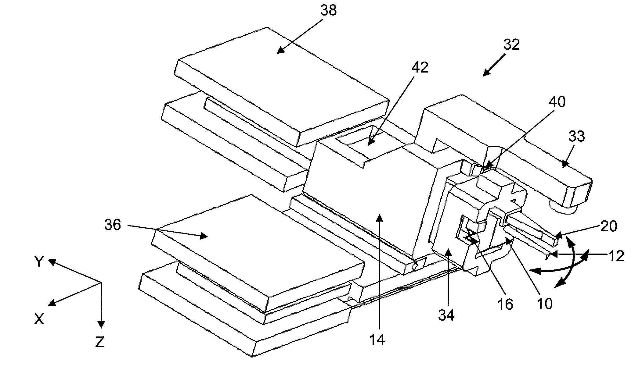
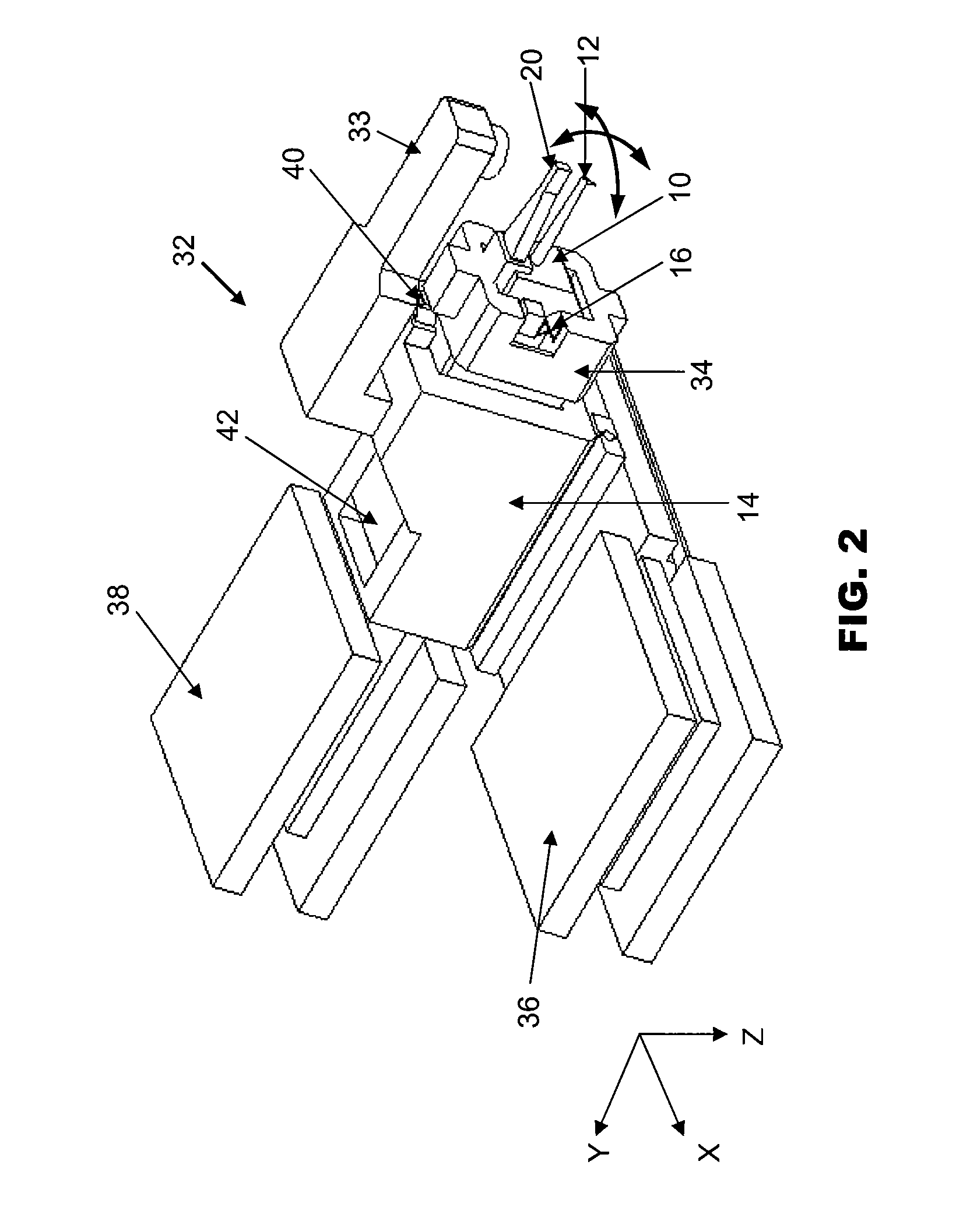
[0020]FIG. 2 is an isometric view of a wire bonding apparatus 32 according to the preferred embodiment of the invention. The wire bonding apparatus 32 includes an optical system 33 located at the top of the apparatus to view a bonding position. A bonding tool in the form of the ultrasonic transducer 12 is mounted on the bondhead body 10. The bondhead body 10 of the bondhead as previously described is contained in a support structure 34 and is pivotally movable on an X flexure bearing 16 that is located between the bondhead body 10 and the support structure 34. Hence, the bondhead body 10 is rotatable relative to the support structure 34. The bondhead body 10 and support structure 34 are mounted on a positioning table in the form of the XY table 30. The XY table 30 further comprises a first motor (such as X-motor 36) and a second motor (such as Y-motor 38) coupled to it to drive the bondhead body 10 to positions along respective first and second orthogonal XY axes.
[0021]The support s...
PUM
| Property | Measurement | Unit |
|---|---|---|
| Angle | aaaaa | aaaaa |
| Distance | aaaaa | aaaaa |
| Distance | aaaaa | aaaaa |
Abstract
Description
Claims
Application Information
 - Generate Ideas
- Intellectual Property
- Life Sciences
- Materials
- Tech Scout
- Unparalleled Data Quality
- Higher Quality Content
- 60% Fewer Hallucinations
Browse by: Latest US Patents, China's latest patents, Technical Efficacy Thesaurus, Application Domain, Technology Topic, Popular Technical Reports.
© 2025 PatSnap. All rights reserved.Legal|Privacy policy|Modern Slavery Act Transparency Statement|Sitemap|About US| Contact US: help@patsnap.com