

Method and system for inflight refueling of unmanned aerial vehicles
- Summary
- Abstract
- Description
- Claims
- Application Information
AI Technical Summary
Benefits of technology
Problems solved by technology
Method used
Image

Examples
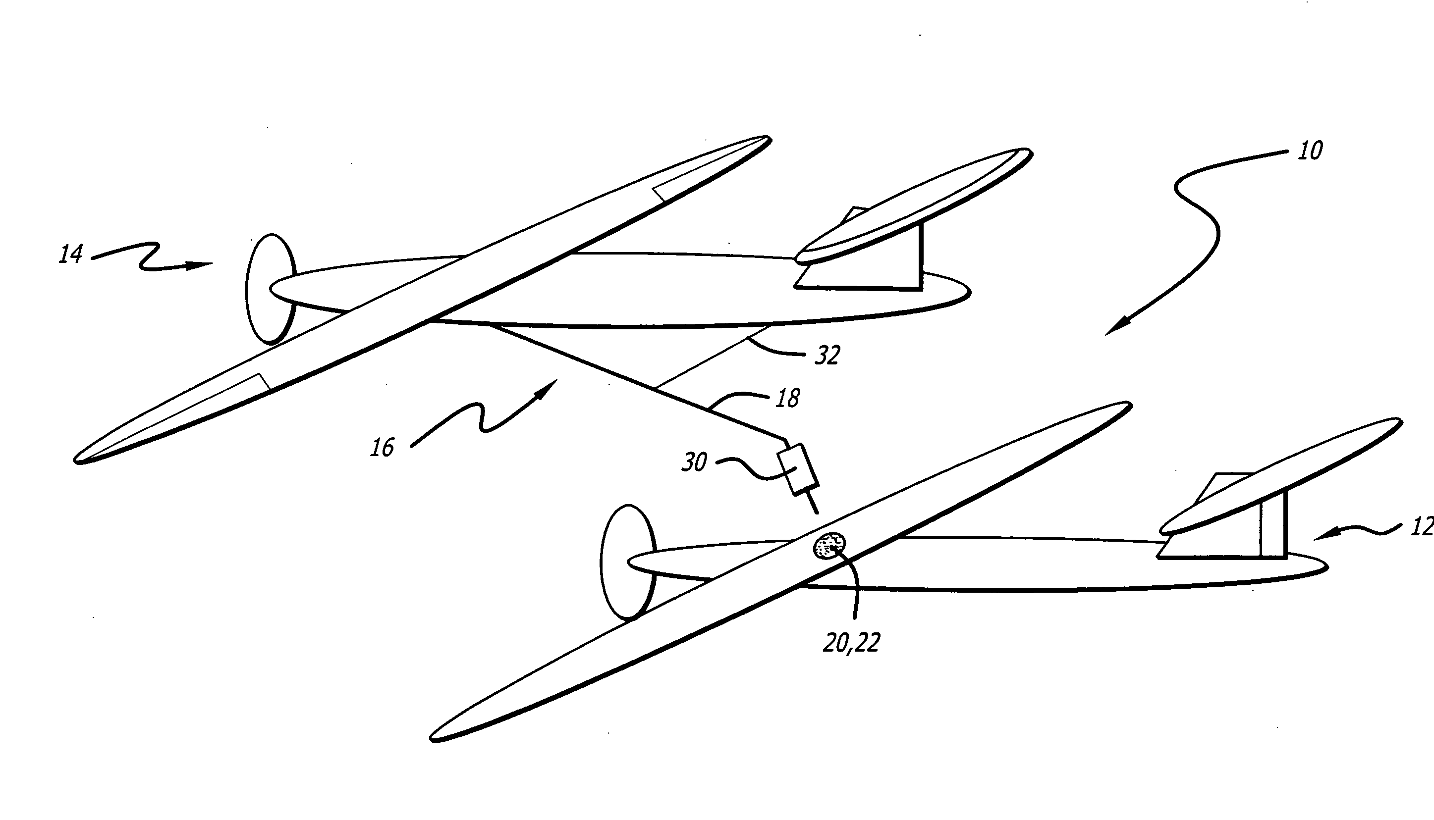
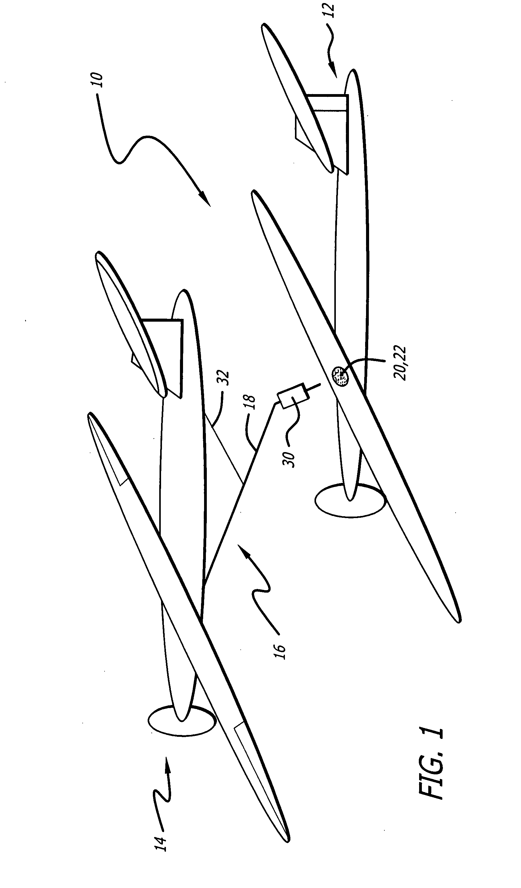
first embodiment
[0072]FIG. 3 is a top view of a section of the mission UAV 12 of FIG. 1 in the coil thereof in accordance with the present teachings. In this embodiment, the coil 20 is disposed around a refueling port or receptacle 22 in an aperture provided in a top surface 26 of the airframe of the mission UAV 12. As shown in FIG. 3, in the best mode, an optional second coil 28 is included for more precise targeting as discussed more fully below.
second embodiment
[0073]FIG. 4 is a side view the mission UAV 12′ of FIG. 1 in a second embodiment in accordance with the present teachings by which the receptor coil 20′ is disposed in a basket 32′ coupled to the UAV via a flexible (e.g. rubber) fuel line 34′.
[0074]FIG. 5 is an end view of an illustrative embodiment of the basket 32′ of FIG. 4. As shown in FIG. 5, the basket 32′ includes a cone 36′ fabricated of metal, plastic, or fabric with a fuel port 22′ disposed at a top center portion thereof in communication with a fuel reservoir (not shown) on the UAV 12. The first coil 20′ is disposed at a distal end of the basket 32′ relative to the fuel port 22′. A second coil 28′ is disposed between the first coil 20′ and the fuel port 22′. Those skilled in the art will appreciate that the invention is not limited to the fabrication of the basket. That is, the basket 32′ may be of a solid, mesh or web construction and / or shaped to fly in a desired manner without departing from the scope of the present te...
PUM
 Abstract
Description
Claims
Application Information