Brake control apparatus and method

a technology of brake control and control apparatus, which is applied in the direction of brake action initiation, vehicle components, braking systems, etc., can solve the problems of inability of brake systems to detect failures, increased stopping distance, and increased danger of panicking drivers, so as to improve safety

Active Publication Date: 2009-02-19
HITACHI ASTEMO LTD
View PDF21 Cites 95 Cited by
  • Summary
  • Abstract
  • Description
  • Claims
  • Application Information

AI Technical Summary

Benefits of technology

[0004]Therefore, it is an object of the present invention to provide brake control apparatus and / or method suitable for detecting a failure in a boost system while a brake operation is not performed, and for improving the safety.

Problems solved by technology

However, since a sensor such as a pressure sensor or a switch is used for detecting a failure in the booster, the brake system is unable to detect a failure until the occurrence of an actual brake operation.
Therefore, if a failure occurs during the brake inoperative period during which there is no brake operation, the brake system requires a time to detect a failure after a start of an actual brake operation, and entails a delay from the start of an brake operation to the start of a brake boosting operation.
Therefore, there arises a time during which the brake system is unable to provide a boosting function, so that the rise of the braking force becomes slower, the brake stopping distance becomes longer, and there is a danger of panicking the driver.

Method used


Image

  • Brake control apparatus and method
  • Brake control apparatus and method
  • Brake control apparatus and method

Examples


first embodiment

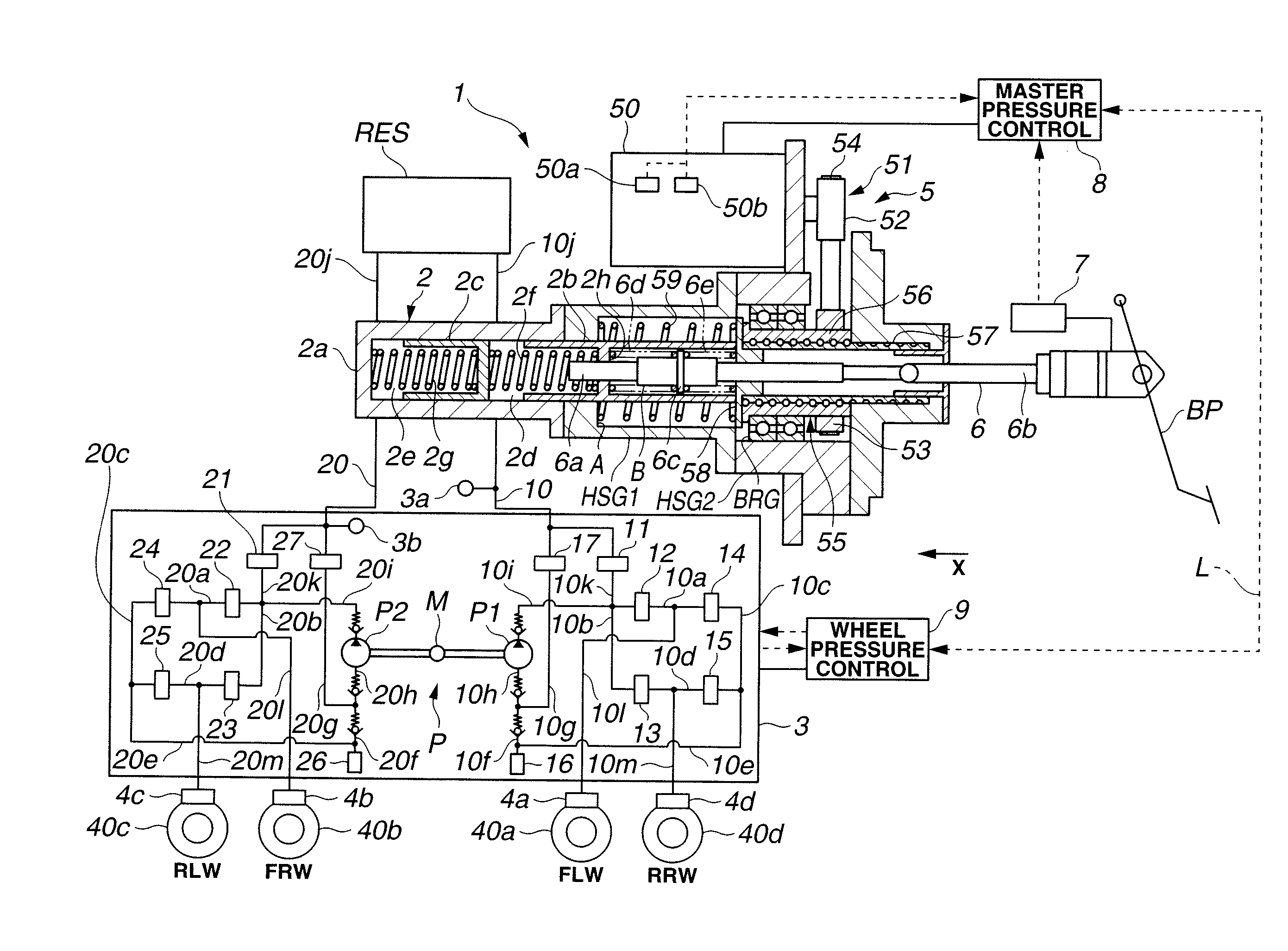
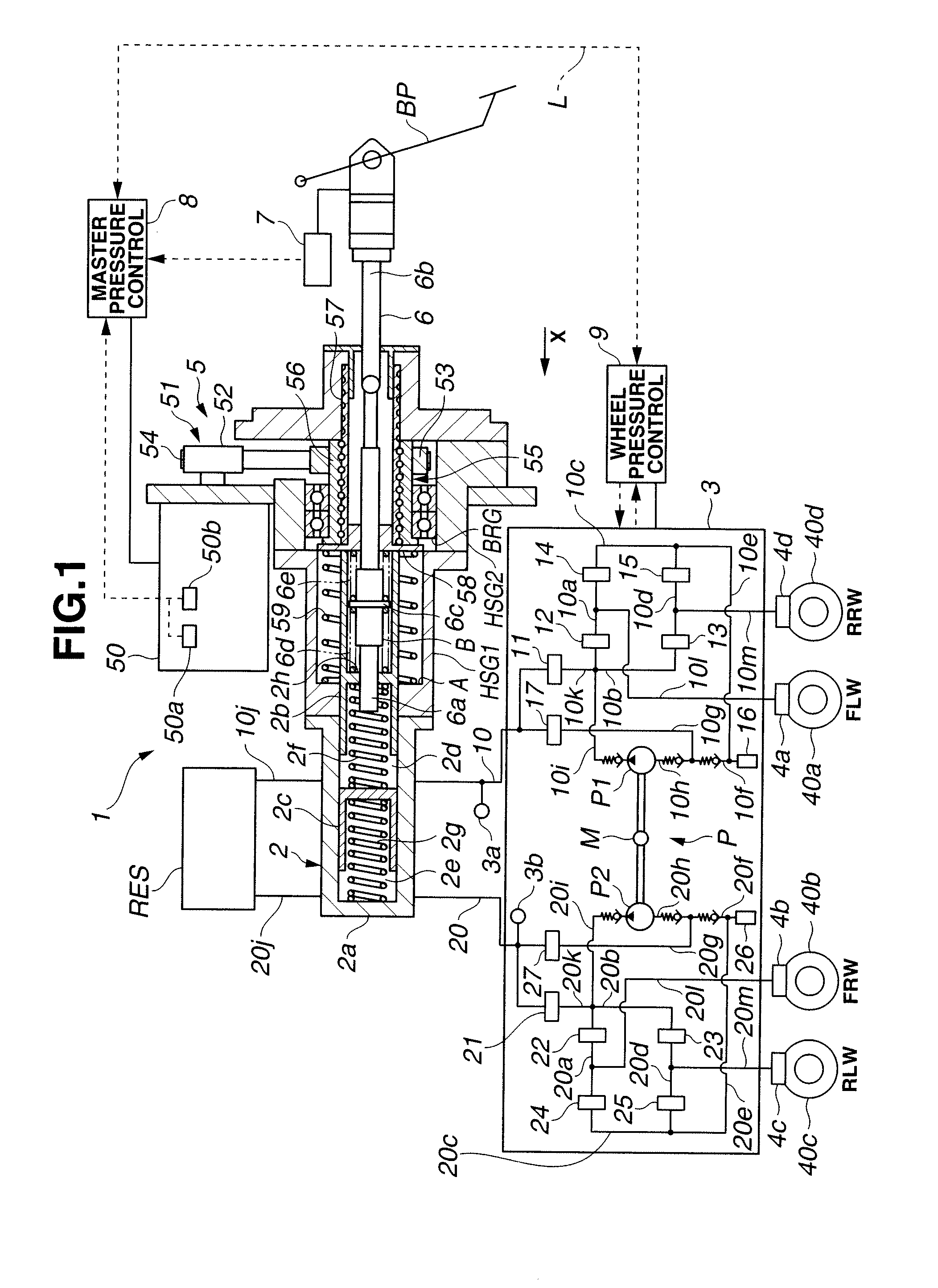
[0014]FIG. 1 schematically shows a vehicle equipped with a brake control system 1 according to the present invention. The vehicle includes front left and right wheels FLW and FRW, and rear left and right wheels RLW and RRW. In FIG. 1, broken line arrows represent signal lines indicating the direction of signal flow.

[0015]Brake control system 1 shown in FIG. 1 includes: a master cylinder 2, a reservoir tank RES; a wheel pressure regulating section or mechanism 3 (which can serve as a hydraulic modulator); four wheel cylinders 4a-4d, respectively, for the four wheels FLW, FRW, RLW and RRW; a master pressure regulating section or mechanism 5 (which can serve as a brake booster) connected with master cylinder 2; an input rod 6; a brake operation sensing device 7; a master pressure control section or device 8 for controlling the master pressure regulating section 5; and a wheel pressure control section or device 9 for controlling the wheel pressure regulating section 3. Master pressure c...

second embodiment

[0151]The brake control system can provide the following effects.

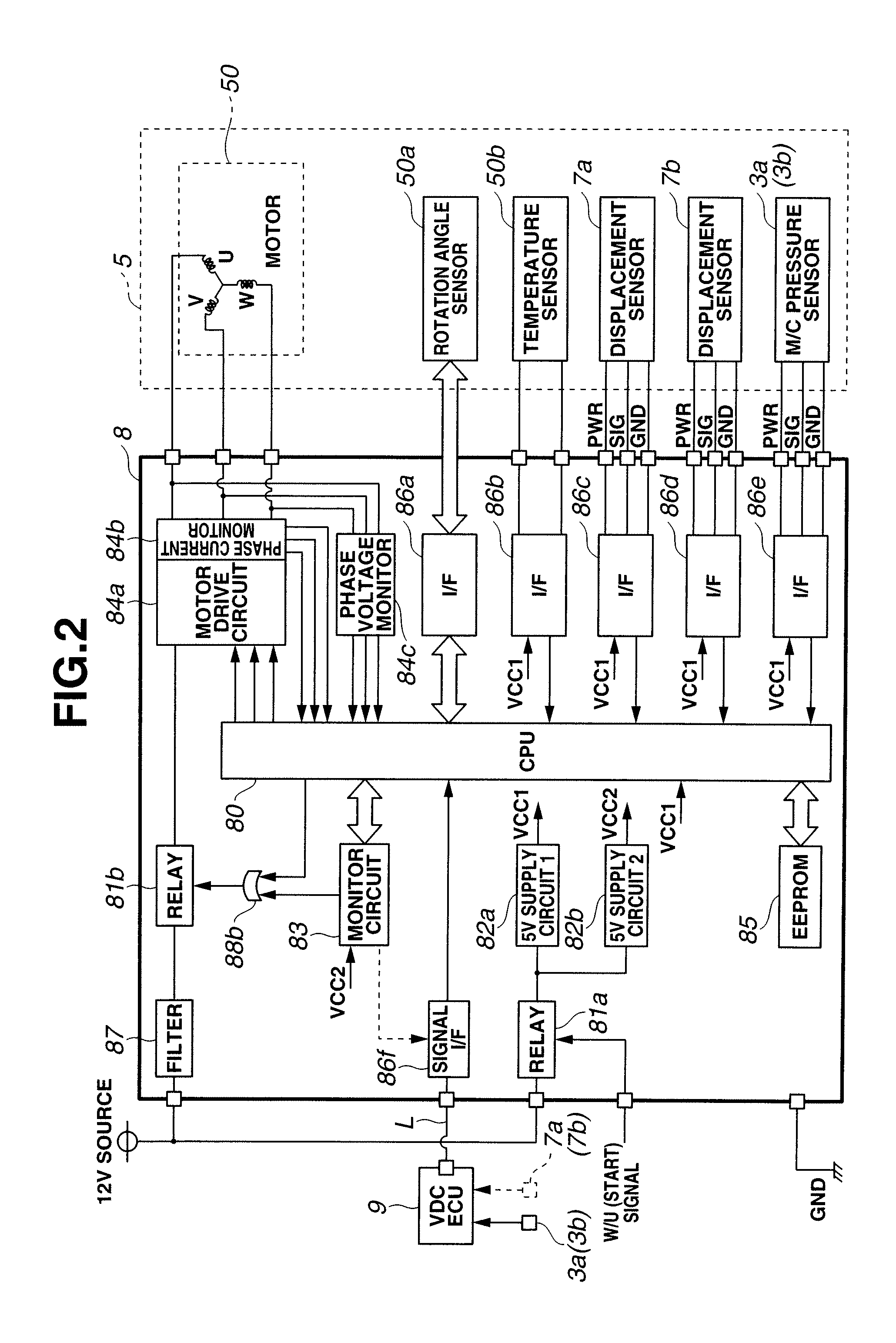
[0152](9) The booster condition transmitting section (86g) is provided in the first control unit or controller (8), the first control unit (8) transmits a condition signal representing a failure, as the booster condition of the booster system, through the CAN communication (or other serial communication or flexray communication) to the second control unit or controller (9), and the second control unit performs the boost backup control to increase the wheel cylinder pressure by controlling the modulator (3) in response to the condition signal signaling the occurrence of a failure.

[0153]By using the CAN communication line (or other serial communication line or flexray communication line), the brake control system can provide effect similar to the before-mentioned effect (3). In the absence of a failure in the boost system (5, 8), the brake control system can performs the variable boost control and / or the automatic brake...


PUM


Abstract

A brake control system includes a master cylinder to produce a master cylinder pressure, a brake booster to assist the master cylinder, a first control unit to control the booster, a hydraulic modulator to supply a wheel cylinder pressure to a wheel cylinder, and a second control unit to control the hydraulic modulator. The hydraulic modulator includes a pressure source, such as a pump, to increase the wheel cylinder pressure. The first and second control units are connected together by a communication line. The brake control system may further include a boost condition transmitting section to transmit, through the communicating line, a condition of a boost system formed by the brake booster and the first control unit.

Description

BACKGROUND OF THE INVENTION[0001]The present invention relates to a brake control apparatus including a brake booster and a hydraulic modulator for regulating a brake fluid pressure and / or a brake control method useful in case of a failure in a brake booster.[0002]A master cylinder operates in response to a driver's brake operation, and supplies a brake operating fluid toward one or more wheel cylinders. A power brake booster is a device to operate the master cylinder in addition to a driver's brake operation, and thereby assist the driver's brake operation. A widely used vacuum brake booster generally utilizes an intake vacuum of an internal combustion engine as power for the booster. In some case, a vacuum pump is utilized in substitution for the engine vacuum. However, the use of the vacuum pump tends to increase the possibility of failure in the brake booster more or less. Accordingly, a published Japanese patent specification JP-A-2001-513041 (≈WO9835867A1) shows technique of p...

Claims


Application Information

Patent Timeline
Patent Type & Authority Applications(United States)
IPC IPC(8): B60T8/48
CPCB60T7/042B60T8/442B60T13/745B60T8/88B60T13/665B60T8/4872
Inventor NISHINO, KIMIOINNAMI, TOSHIYUKIMATSUBARA, KENICHIROSUGAWARA, TOSHIHARU
Owner HITACHI ASTEMO LTD
Why Eureka
Try Eureka