
Transmission apparatus and transmission method

a transmission apparatus and transmission method technology, applied in the field of transmission apparatus and transmission method, can solve the problem of difficult and achieve the effect of easy control of the probability of transmission errors

Active Publication Date: 2009-02-19
CANON KK
View PDF18 Cites 20 Cited by
  • Summary
  • Abstract
  • Description
  • Claims
  • Application Information

AI Technical Summary

Benefits of technology

[0006]Accordingly, the present invention allows for easily controlling the probability of the occurrence of transmission errors based on the layer importance.
[0008]Since a transmission pattern is determined for each layer according to the present invention, it becomes possible to easily control the probability of the occurrence of a transmission error based on the layer importance. Therefore, it becomes possible to reduce the probability of the occurrence of an error in the transmission of a packet of a layer with high importance, for example.

Problems solved by technology

Therefore, it has been difficult to control the probability of the occurrence of transmission errors based on the layer importance.

Method used


Image

  • Transmission apparatus and transmission method
  • Transmission apparatus and transmission method
  • Transmission apparatus and transmission method

Examples


first embodiment

[0021]Hereinafter, a first embodiment of the present invention will be described with reference to the attached drawings.

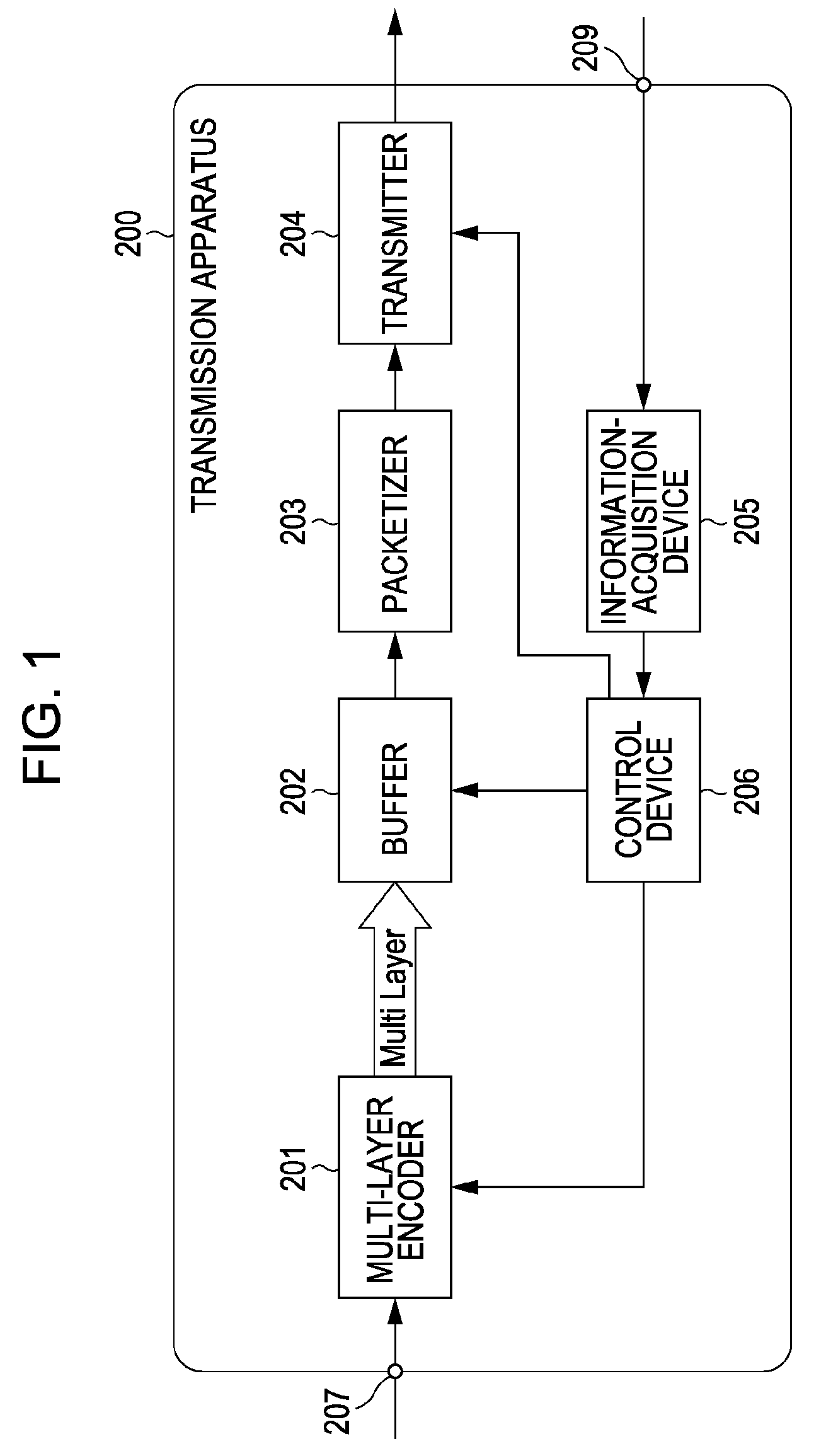
[0022]FIG. 1 shows an example of the configuration of a transmission apparatus 200. In the transmission apparatus 200, digital-video signals are transmitted to a multi-layer encoder 201 via an input end 207. If the multi-layer encoder 201 has an analog-to-digital (A / D) conversion function, analog-video signals are transmitted to the multi-layer encoder 201 via the input end 207, and digital-video signals are generated in the multi-layer encoder 201.

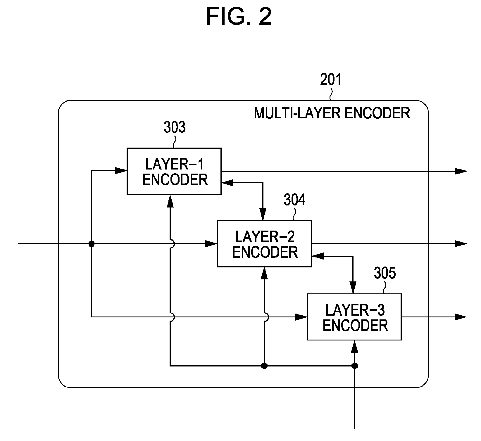
[0023]FIG. 2 shows an example of the configuration of the multi-layer encoder 201. In FIG. 2, the multi-layer encoder 201 includes a layer-1 encoder 303, a layer-2 encoder 304, and a layer-3 encoder 305. Activation and non-activation of each of the layer-1 encoder 303, the layer-2 encoder 304, and the layer-3 encoder 305 can be separately controlled by using a control device 206 shown in FIG. 1. The multi-layer encoder ...

second embodiment

[0084]Next, a second embodiment of the present invention will be described. In the description of the second embodiment, the same components as those of the first embodiment will be designated by the same reference numerals as those shown in FIGS. 1 to 7, so that detailed descriptions of the same components will be omitted.

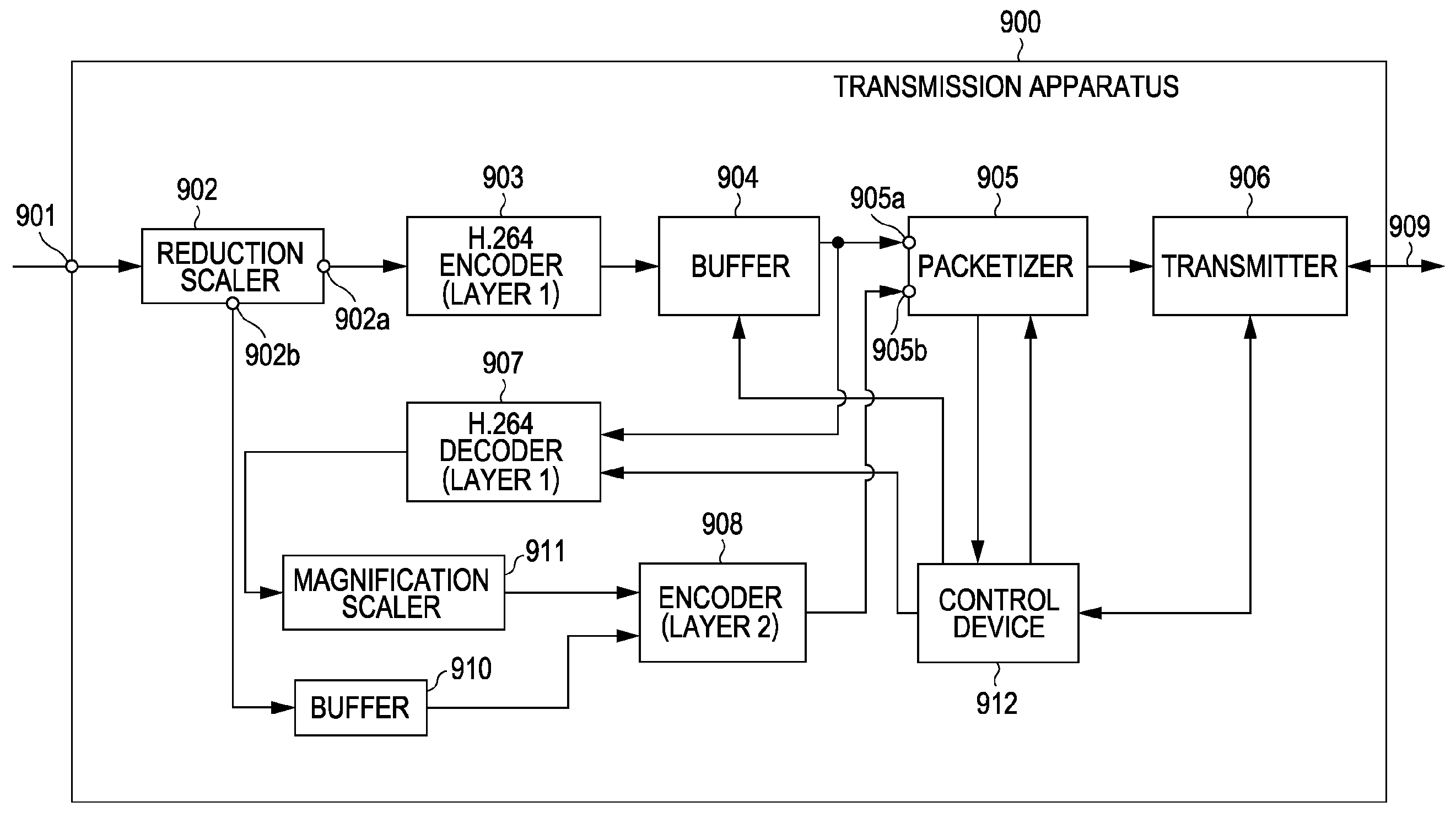
[0085]FIG. 8 shows an example of the configuration of a transmission apparatus 900. In the second embodiment, the digital-video signals corresponding to 3840×2160 [pixels] (images of the layer 2 shown in FIG. 9) are transmitted to a reduction scaler 902 via an input end 901, for example.

[0086]The reduction scaler 902 generates the digital-video signals corresponding to 1920×1080 [pixels] (images of the layer 1 shown in FIG. 9) by vertically and horizontally reducing the image corresponding to the transmitted digital-video signals to one half the original image. The reduction scaler 902 transmits the generated digital-video signals from an end 902a to an H.264 enco...


PUM


Abstract

A transmission apparatus of the present invention includes an encoder unit configured to encode data including plural layers for each of the layers, a packetizing unit configured to generate a packet based on the data encoded by the encoder unit, a determination unit configured to determine transmission intervals at which the generated packet is transmitted for each of the layers, and a transmission unit configured to transmit the generated packet at the determined transmission intervals, wherein the transmission intervals are changed for each specified packet, where the change varies with each of the plurality of layers.

Description

BACKGROUND OF THE INVENTION[0001]1. Field of the Invention[0002]The present invention relates to a transmission apparatus and a transmission method, and particularly relates to a transmission apparatus and a transmission method that are suitable for transmitting a packet.[0003]2. Description of the Related Art[0004]Hitherto, technologies to transmit data including plural layers on a layer-to-layer basis have been developed. As an example of the above-described technologies, Japanese Patent Laid-Open No. 2004-140651 discloses the technology for distributing a code amount on time base by providing an offset at the time when encoding performed in frames for each of the layers is started. Thus, the code amount is distributed on the time base, which makes it possible to decrease a local transmission rate without changing a transmission rate determined on a per-unit-time basis, and reduce packet losses due to traffic.[0005]According to known technologies, however, the concentration of the...

Claims


Application Information

Patent Timeline
IPC IPC(8): H04J3/00H04L1/00H04L47/431H04L47/80H04N19/00H04N19/102H04N19/166H04N19/196H04N19/33H04N19/37H04N19/503H04N19/59H04N19/65H04N19/66H04N19/70
CPCH04L1/0006H04L2001/0098H04N19/36H04N19/33H04N19/31H04N19/61
Inventor HAMANAKA, AKIYOSHI
Owner CANON KK
Learn More