Moving image coding apparatus and moving image decoding apparatus

a coding apparatus and moving image technology, applied in the direction of signal generators with optical-mechanical scanning, color television with bandwidth reduction, etc., can solve the problems of reducing whole coding efficiency, unable to adapt to the changing of the size of the macro block, and unable to change the size of the whole coding block according to the change of the coding block, etc., to achieve the effect of suppressing the increase in rectangular size information

Active Publication Date: 2009-02-19
MITSUBISHI ELECTRIC CORP
View PDF6 Cites 124 Cited by
  • Summary
  • Abstract
  • Description
  • Claims
  • Application Information

AI Technical Summary

Benefits of technology

[0011]Because the moving image coding apparatus in accordance with the present invention determines the size of each of the rectangular regions for each frame or each sequence which is a set of a plurality of continuous frames, the moving image coding apparatus can code the image while changing the rectangular region size adaptively, and can suppress the increase in the rectangular size information of the coded image due to this changing.

Problems solved by technology

A problem with such the conventional image coding / decoding method is that because the macro block size is fixed, the macro block size cannot be changed adaptively according to the resolution of the image or the descriptions of the image (the fineness of a pattern of the image, the intensity of a motion in the image, etc.).
In such a case, because the overhead due to coding mode information and motion vector information which are coded in units of each macro block increases though the prediction efficiency does not increase, the whole coding efficiency decreases.
However, because switching of the coding mode in units of a unit region having a smaller size than the macro block size cannot be performed, the prediction efficiency in the vicinity of a boundary of a region having large intensity of motion or a region including different motions (a person and a background, or the like) decreases, and therefore the coding efficiency decreases.
Furthermore, a problem with the technology disclosed by above-mentioned conventional patent reference 1 is that because the size is changed adaptively within each frame, the amount of codes of the rectangular size information is large.

Method used


Image

  • Moving image coding apparatus and moving image decoding apparatus
  • Moving image coding apparatus and moving image decoding apparatus
  • Moving image coding apparatus and moving image decoding apparatus

Examples


embodiment 1

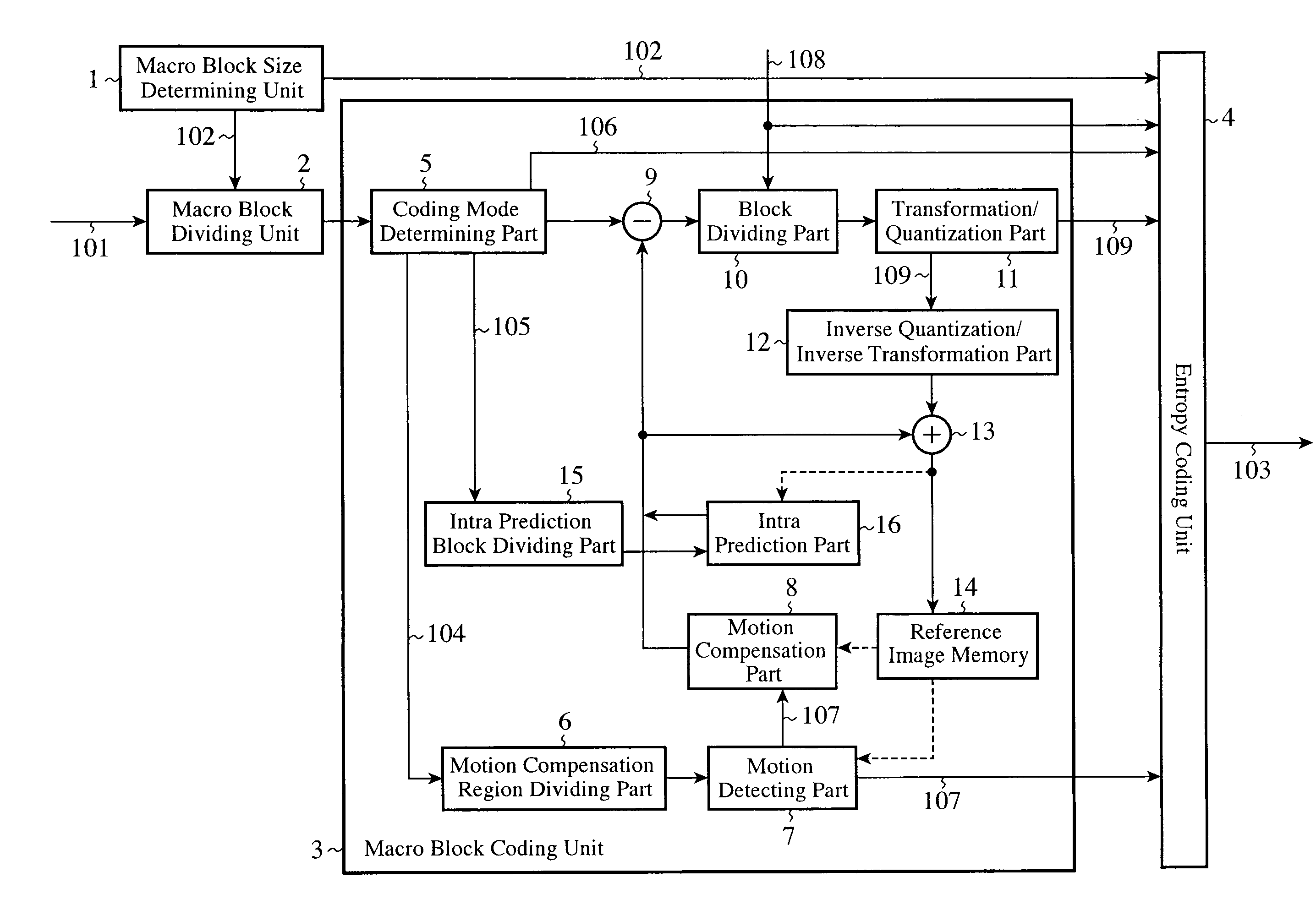
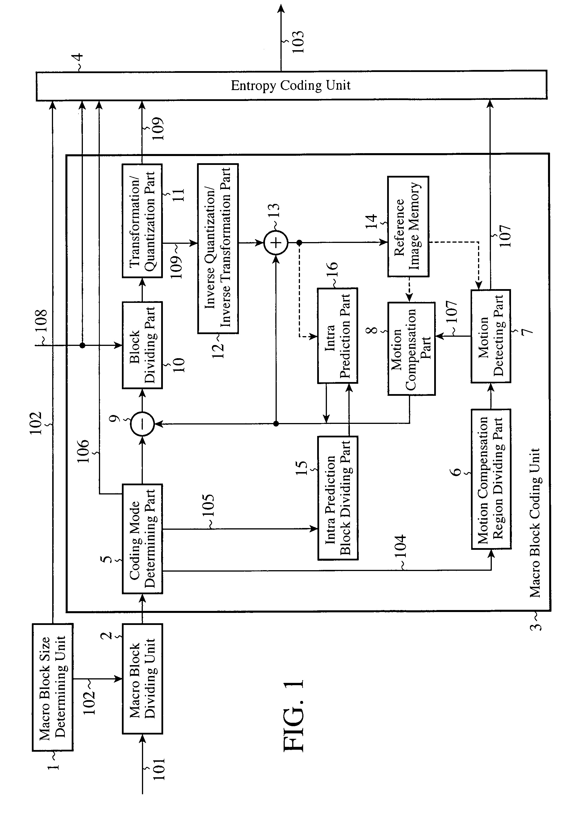
[0020]FIG. 1 is a block diagram showing a moving image coding apparatus in accordance with Embodiment 1 of the present invention.

[0021]In the figure, the moving image coding apparatus is provided with a macro block size determining unit (a rectangular region size determining means) 1, a macro block dividing unit (a rectangular region dividing means) 2, a macro block coding unit (a rectangular region coding means) 3, and an entropy coding unit (a rectangular region size information multiplexing means) 4. The macro block coding unit 3 is provided with a coding mode determining part (a coding mode determining means) 5, a motion compensation region dividing part (a motion compensation region dividing means) 6, a motion detecting part (a motion detecting means) 7, a motion compensation part (a motion compensation means) 8, a subtractor 9, a block dividing part (a block dividing means) 10, a transformation / quantization part (a transformation / quantization means) 11, an inverse quantization...

embodiment 2

[0057]Embodiment 2 relates to a moving image decoding apparatus which decodes a bit stream which is coded with the macro block size being selected independently on a frame-by-frame basis.

[0058]FIG. 7 is a block diagram of the moving image decoding apparatus in accordance with Embodiment 2.

[0059]In the figure, the moving image decoding apparatus is provided with an entropy decoding unit 21 and a macro block decoding unit (a rectangular region decoding means) 22. In this case, the entropy decoding unit 21 is a processing unit which performs entropy decoding on an inputted bit stream 201, and which implements a rectangular region size determination means for determining the size of each of rectangular regions in units of each frame or in units of each sequence which is a set of a plurality of continuous frames, a coding mode decoding means for decoding a coding mode which is determined for each rectangular region, a motion-vector-information decoding means for decoding motion vector in...


PUM


Abstract

A macro block size determining unit 1 determines the size of each macro block on a frame-by-frame basis. A macro block dividing unit 2 divides an inputted image into macro blocks each having the size determined by the macro block size determining unit 1. A macro block coding unit 3 determines a coding mode for each of the macro blocks divided by the macro block dividing unit 2, and codes pixel values in each of the macro blocks in the determined coding mode.

Description

FIELD OF THE INVENTION[0001]The present invention relates to a moving image coding apparatus which divides a moving image into rectangular regions and codes the moving image in units of the rectangular regions, and a moving image decoding apparatus which decodes a coded moving image in units of rectangular regions.BACKGROUND OF THE INVENTION[0002]As a conventional method of coding or decoding an image signal, there has been provided MPEG-4 (Moving Picture Experts Group Phase-4) visual (ISO / IEC 14496-2). MPEG-4 is a method of regarding a moving image sequence as a collection of moving image objects each of which has an arbitrary shape in space and in time, and performing coding and decoding the moving image sequence in units of each moving image object.[0003]In MPEG-4, each moving image object including a time axis is referred to as a Video Object, each element of a Video Object is referred to as a Video Object Layer (VOL), each element of a VOL is referred to as a Group of Video Obj...

Claims


Application Information

Patent Timeline
Patent Type & Authority Applications(United States)
IPC IPC(8): H04N7/12H04N19/119H04N19/136H04N19/169H04N19/172H04N19/196H04N19/46H04N19/50H04N19/593H04N19/60H04N19/61H04N19/70H04N19/91
CPCH04N7/50H04N19/50H04N19/61H04N19/51H04N19/176H04N19/124H04N19/44H04N19/105H04N19/139H04N19/167H04N19/182H04N19/543H04N19/119H04N19/137H04N19/13H04N19/159H04N19/172
Inventor MORIYA, YOSHIMISEKIGUCHI, SHUNICHIYAMADA, YOSHIHISAASAI, KOHTARO
Owner MITSUBISHI ELECTRIC CORP
Why Eureka
Try Eureka