Imaging device, driving method therefor and imaging method

Inactive Publication Date: 2009-02-19
CANON KK
View PDF8 Cites 8 Cited by
  • Summary
  • Abstract
  • Description
  • Claims
  • Application Information

AI Technical Summary

Benefits of technology

[0016]The present invention has been made to overcome the conventional drawbacks, and has as its o

Problems solved by technology

However, if even one of 2×2 pixels is defective, the pixel after the addition process (or averaging process) must be treated as a defective pixel.
In this case, the defective pixel greatly degrades a reduced image.
The 2D sensor is formed from a semiconductor, and it is generally difficult to prevent generation of any defect in many pixels during the manufacturing

Method used


Image

  • Imaging device, driving method therefor and imaging method
  • Imaging device, driving method therefor and imaging method
  • Imaging device, driving method therefor and imaging method

Examples


Example

First Embodiment

[0045]The first embodiment of the present invention will be described.

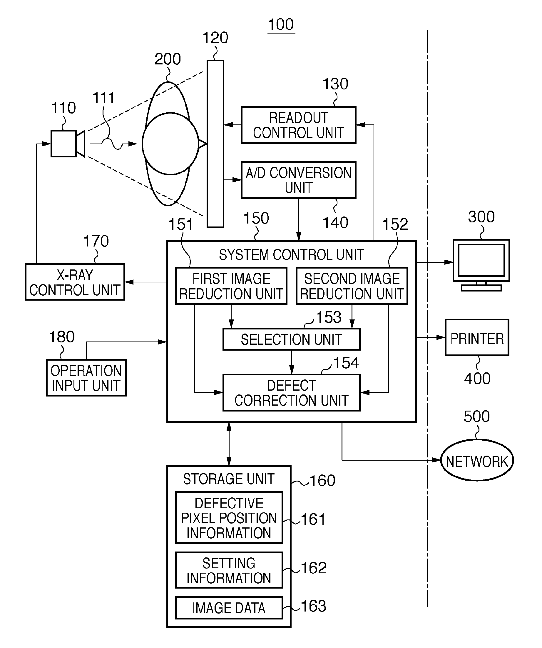
[0046]FIG. 3 is a schematic view showing an example of the schematic configuration of an X-ray imaging system including an X-ray imaging device according to the first embodiment of the present invention.

[0047]The X-ray imaging system shown in FIG. 3 comprises an X-ray imaging device 100 according to the first embodiment, a monitor 300, a printer 400, and a network 500.

[0048]The X-ray imaging device 100 comprises an X-ray generation unit 110, imaging unit 120, readout control unit 130, A / D conversion unit 140, system control unit 150, storage unit 160, X-ray control unit 170, and operation input unit 180. An object 200 is placed at a predetermined position between the X-ray generation unit 110 and the imaging unit 120.

[0049]The X-ray generation unit 110 generates X-rays 111 under the control of the X-ray control unit 170. More specifically, in the first embodiment, the X-ray generation unit 110 emit...

Example

Second Embodiment

[0103]The second embodiment of the present invention will be described.

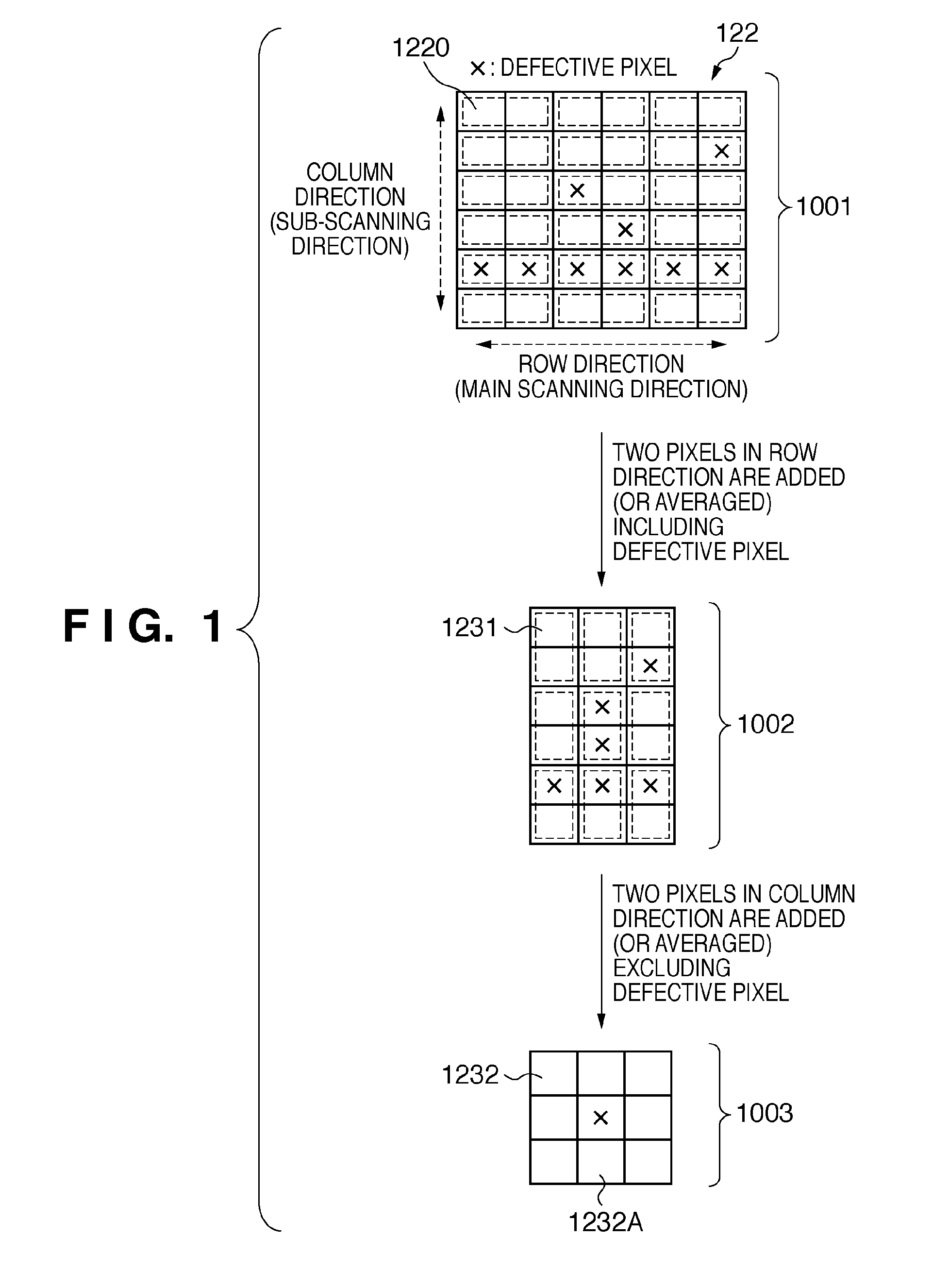
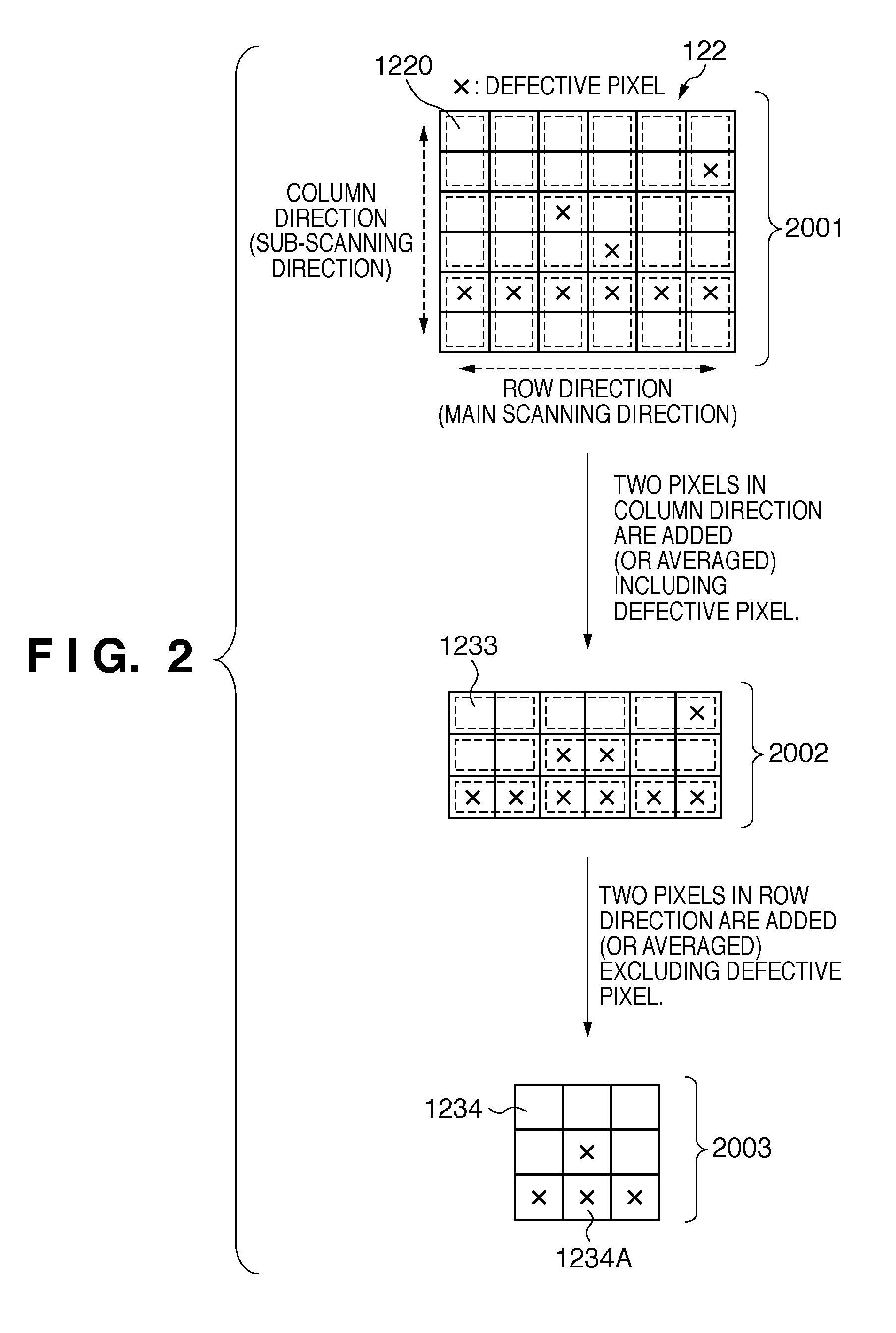
[0104]The schematic configuration of an X-ray imaging system including an X-ray imaging device according to the second embodiment is the same as that of the X-ray imaging system including the X-ray imaging device according to the first embodiment shown in FIG. 3. In the first embodiment, the selection unit 153 determines, for the entire 2D sensor 122, which of the first image reduction process by the first image reduction unit 151 or the second image reduction process by the second image reduction unit 152 is to be executed. To the contrary, in the second embodiment, a selection unit 153 determines, every plurality of rows in a 2D sensor 122, which of the first image reduction process by a first image reduction unit 151 or the second image reduction process by a second image reduction unit 152 is to be executed. That is, the selection unit 153 determines, for each readout unit of pieces of pixel ...


PUM


Abstract

An imaging device includes an imaging unit (120) having a sensor in which pixels including a defective pixel are arrayed in a matrix, and sensing an image, a first image reduction unit (151) reducing the image by adding pieces of pixel information of pixels adjacent in the row direction in the sensor including pixel information of the defective pixel, and adding pieces of pixel information of pixels adjacent in the column direction excluding pixel information of the defective pixel, a second image reduction unit (152) reducing the image by adding pieces of pixel information of pixels adjacent in the column direction in the sensor including pixel information of the defective pixel, and adding pieces of pixel information of pixels adjacent in the row direction excluding pixel information of the defective pixel, and a selection unit (153) selecting the unit (151) or the unit (152) when reducing the image.

Description

BACKGROUND OF THE INVENTION[0001]1. Field of the Invention[0002]The present invention relates to an imaging device having a sensor in which pixels are arrayed in a matrix, and a driving method therefor and, more particularly, to an imaging device which senses an image associated with radiation such as X-rays entering the sensor, and a driving method therefor.[0003]2. Description of the Related Art[0004]Recently, digital X-ray imaging devices with a photoelectric conversion element are being used to acquire the intensity distribution of X-rays having passed through an object in radiography using, for example, X-rays which are a kind of radiation.[0005]The digital X-ray imaging device is superior in sensitivity and image quality to a conventional film type imaging device. Since the digital X-ray imaging device can save an image as digital data, an image obtained by radiographing (imaging) an object can be processed by various image processes into one which makes diagnosis easier. The ...

Claims


Application Information

Patent Timeline
IPC IPC(8): G06K9/60H04N5/32H04N5/335H04N5/367H04N5/369H04N5/374H04N5/378
CPCG06T3/4007
Inventor KONISHI, SHINPEI
Owner CANON KK
Why Eureka
Try Eureka