Heat transfer device: seal and thermal energy contact units

a technology of contact unit and heat transfer device, which is applied in the field of negative pressure and thermal energy transfer unit, can solve the problems of tightening effect, leakage of seal or passing air at the user/seal interface, and inability to maintain a complete seal

Inactive Publication Date: 2009-02-19
STRYKER CORP
View PDF99 Cites 44 Cited by
  • Summary
  • Abstract
  • Description
  • Claims
  • Application Information

AI Technical Summary

Benefits of technology

[0020]The improvements to the soft seal and the thermal energy transfer device, and some modifications of the enclosure, are

Problems solved by technology

In practice, however, a “hard” seal can produce a tourniquet effect.
Also, any inability to maintain a complete seal will be problematic in a system requiring as much.”
Indeed, in response to user movement, such a seal may leak or pass some air at the user/seal interface.
Increased tissue interface pressure is undesirable.
The patient's election may be uninte

Method used


Image

  • Heat transfer device: seal and thermal energy contact units
  • Heat transfer device: seal and thermal energy contact units
  • Heat transfer device: seal and thermal energy contact units

Examples


first embodiment

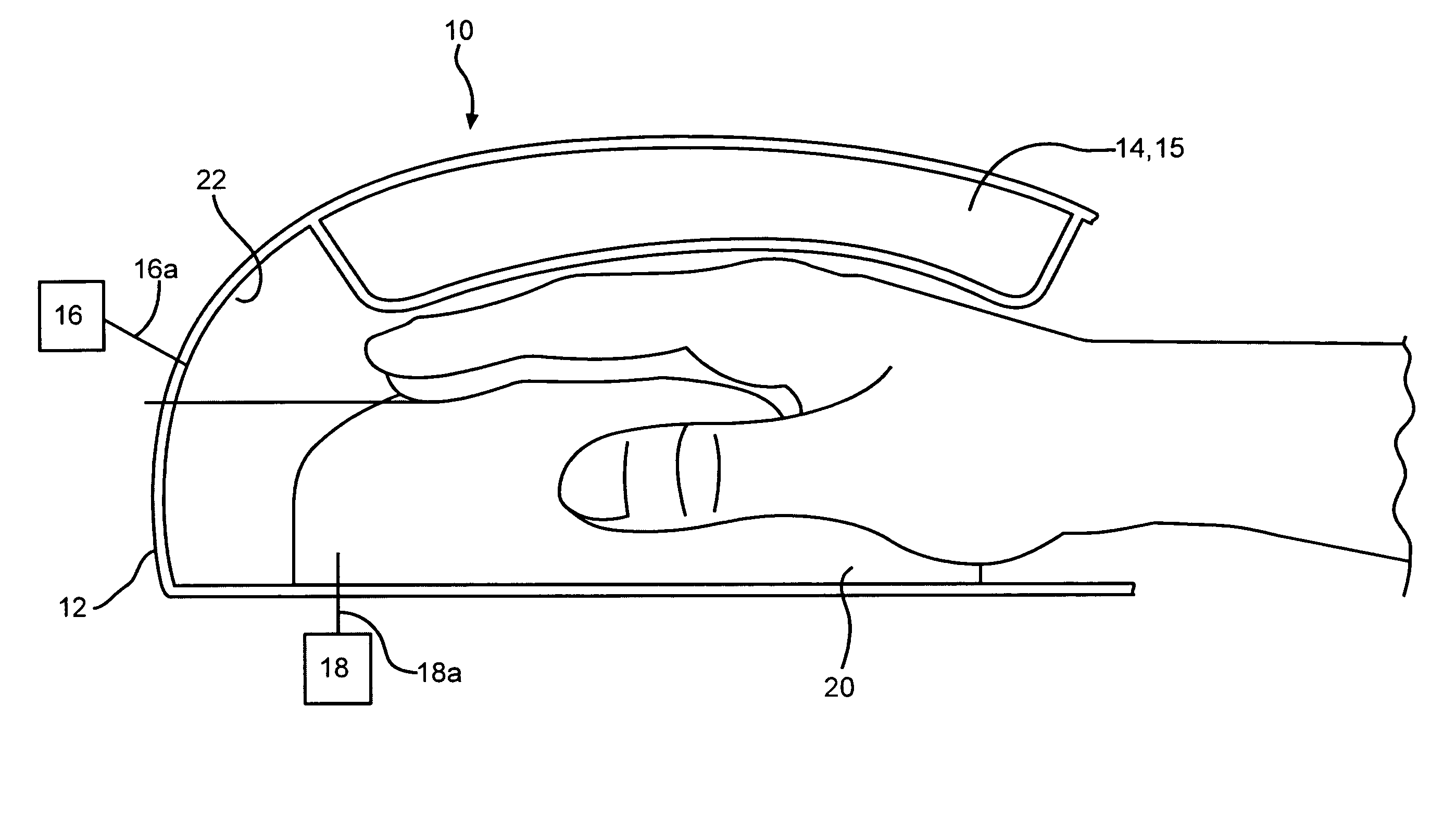
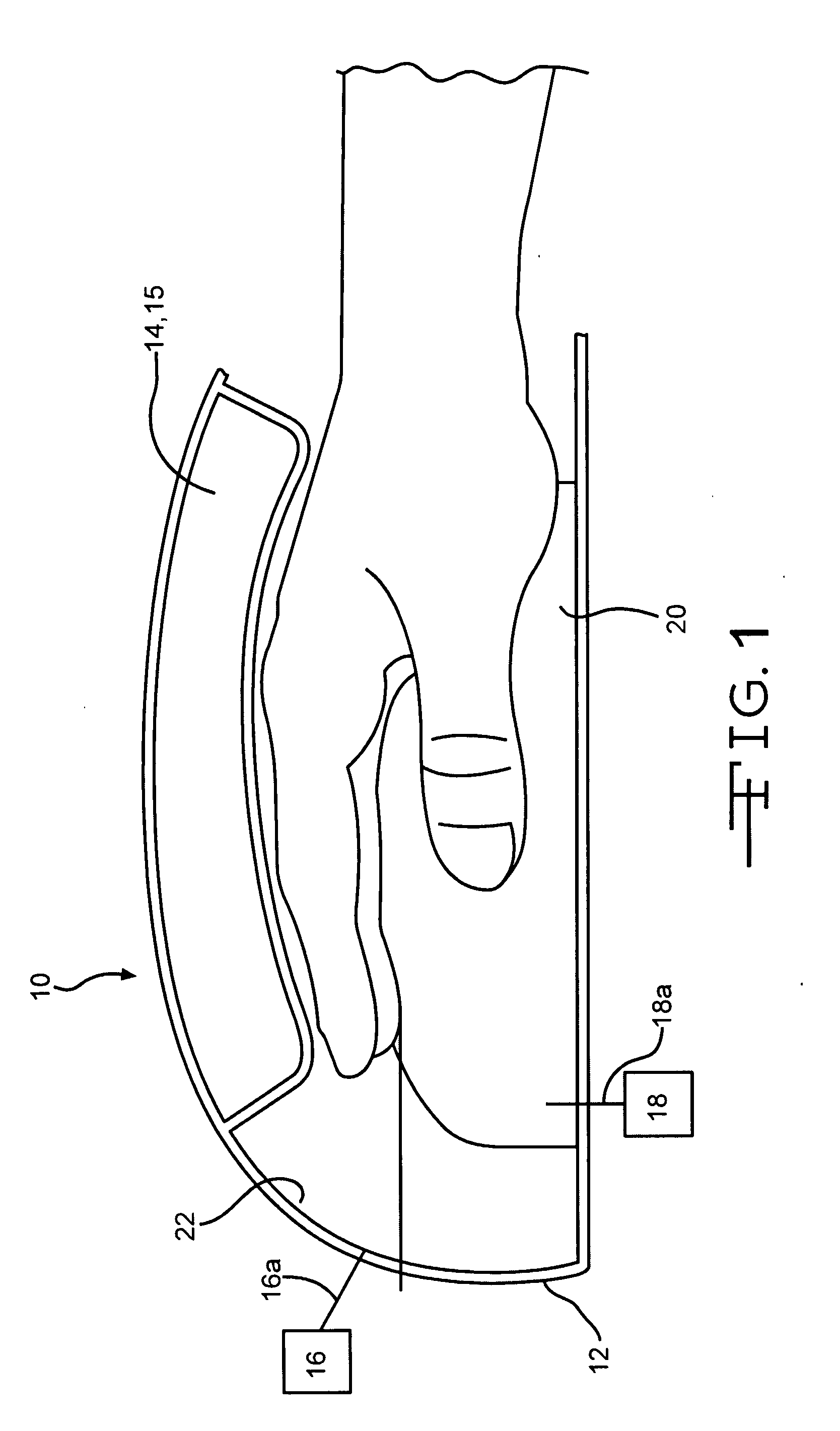
[0028]A first embodiment of the negative pressure, thermal energy device 10 is illustrated in FIG. 1. In FIG. 1, the thermal energy contacting element 20 has a symmetric design to accommodate both small and large hands, and can have a fluid and / or a resistor system. The seal is a critical element in this embodiment.

[0029]The seal 14 is a bladder seal 15. The bladder seal 15 and the thermal energy contacting element 20 are positioned in the interior of the enclosure 12. In particular the bladder seal 15 and the thermal energy contacting element 20 are positioned on the opposite sides of the interior surface 22 of the enclosure 12, as illustrated in FIG. 1. The bladder seal 15 receives a fluid at a predetermined pressure. Preferably the predetermined pressure in the bladder seal 15 is around 32 mmHg.

[0030]The bladder seal 15 inflates to the predetermined pressure when the patient's venous plexus area is properly positioned on the thermal energy contacting element 20.

[0031]The fluid in...

second embodiment

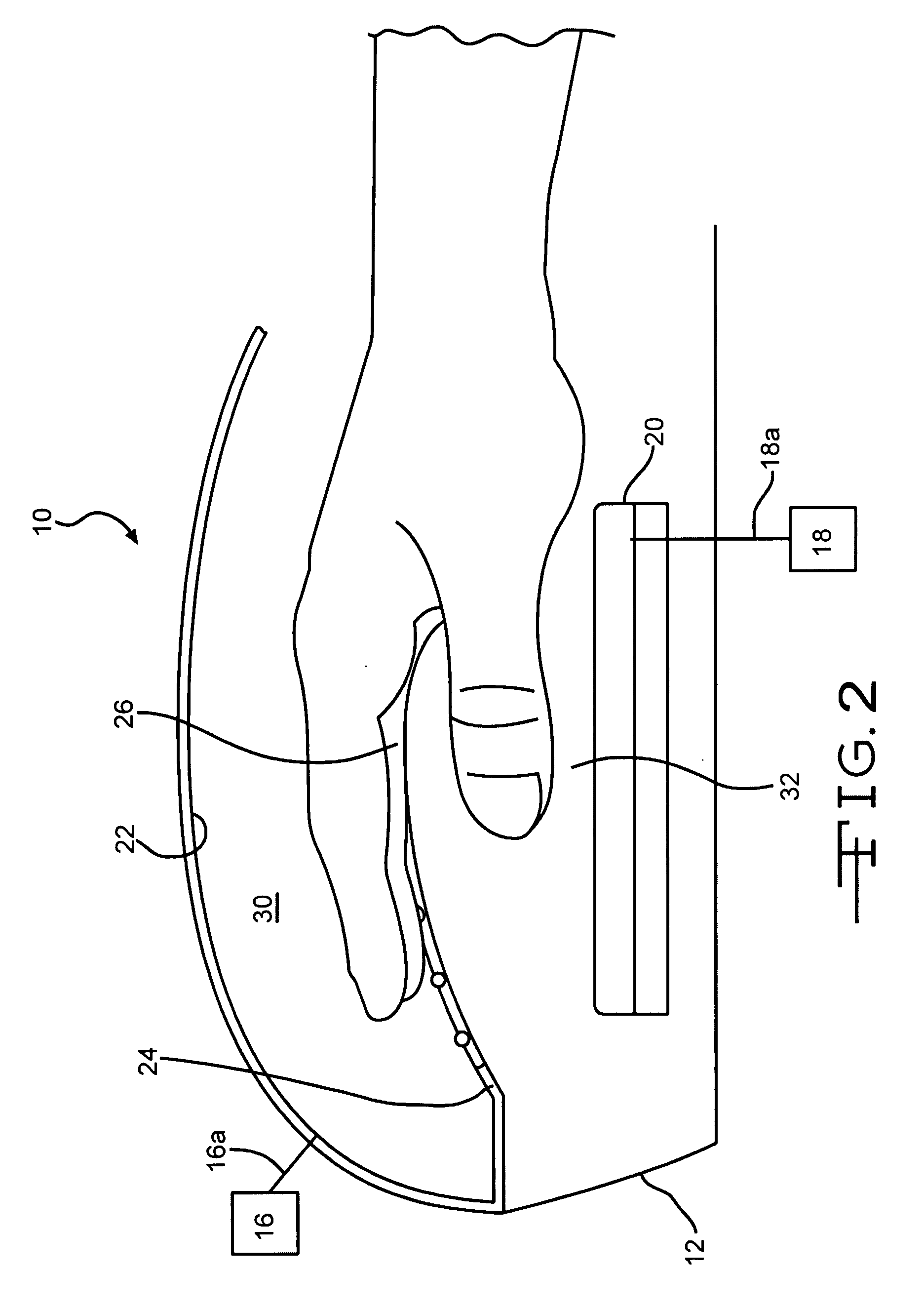
[0035]FIG. 2 illustrates variations of the enclosure 12 and the thermal energy contacting element 20. The enclosure 12 has the interior surface 22, and extending from the interior surface 22 is a mezzanine layer 24.

[0036]The mezzanine layer 24 divides the enclosure's 12 interior into two sections. The first section 30 receives the patient's body portion. The second section 32 contains the thermal energy contacting element 20. The thermal energy contacting element 20 can be (a) a light source that radiates heat having a narrow or a broad band of non-ionizing light (500 to 2000 nm), or (b) a cold source, for example, dry ice, that extracts thermal energy from the patient's venous plexus area.

[0037]The mezzanine layer 24 is a material that allows the radiant thermal energy from (a) the thermal energy contacting element 20 to pass through it or (b) the patient's venous plexus area to pass through it.

[0038]The light source embodiment, on first blush, may seem similar to the prior art's h...

third embodiment

[0042]The third embodiment is illustrated in FIG. 3. The third embodiment is similar to the second embodiment. A difference between the third and the second embodiments is that the thermal sensors 26 are embedded and / or attached to a fitting material 34 (for example, a glove, a mitten, and / or a sock) positioned over the patient's body portion that enters the enclosure 12. In particular the thermal sensors 26 are positioned next to the patient's venous plexus area as illustrated in FIG. 3.

[0043]Preferably, the first fitting material 34 is a black material to retain the thermal energy transferred to the patient.

[0044]In addition, a slight negative pressure from the vacuum system 16 though conduit 16b could be applied to the interior portion of the first fitting material 34. The conduit 16b could have, or not have, valves and check valves to ensure the pressure in the first fitting material 34 is the same or different from the negative pressure in the first section 30 of the enclosure ...


PUM


Abstract

A device has four fundamental components: an enclosure, a soft seal, a vacuum system and a thermal energy system having a thermal energy contacting element. The device provides thermal energy therapy and negative pressure therapy device simultaneously and/or in conjunction to a patient. The device has a thermal energy system that is more efficient in thermal energy transfer and the soft seal decreases tissue interface pressure to obtain the desired soft seal effect.

Description

FIELD OF THE INVENTION [0001]The present invention relates to negative pressure, thermal energy transfer units for controlling, maintaining and / or adjusting the body core temperature of a mammal, in particular a human.BACKGROUND OF THE INVENTION[0002]Stanford University is the assignee of U.S. Pat. Nos. 5,683,438; 6,602,277; 6,673,099; 6,656,208; 6,966,922; 7,122,047; and 6,974,442. These patents disclose a negative pressure, thermal energy device that can be applied to a patient. The negative pressure device has the following elements: (1) an enclosure having an opening to receive a portion of a patient's body that contains a non-hairy skin region overlaying the subcutaneous arteriovenous anastomoses (AVAs) and venous plexuses (henceforth the non-hairy skin region and underlying area is collectively referred to as a “venous plexus area”), (2) a vacuum system that creates a negative pressure in the enclosure, (3) a seal positioned at the enclosure's opening to maintain the negative ...

Claims


Application Information

Patent Timeline
IPC IPC(8): A61F7/00
CPCA61F7/0053A61N2005/0645A61F2007/0086A61H9/0057A61H2201/0207A61H2201/0214A61H2201/0228A61H2201/0242A61H2201/025A61H2201/0257A61H2201/0264A61H2201/10A61H2205/065A61N5/06A61F2007/0036
Inventor PERET, JAMESGRISANTI, LAURA C.KEDGE, GERARD E.CAZZINI, KARLMCGEE, JAMES
Owner STRYKER CORP
Why Eureka
Try Eureka