
Model set adaptation by probability mass diffusion

a probability mass diffusion and model technology, applied in the field of stochastic model prediction, can solve the problems of high computational burden, high possibility, complex computational task of prediction based on elliptical gaussian probability function, etc., and achieve the effect of easing computational burden

Inactive Publication Date: 2009-02-19
KRONHAMN THOMAS
View PDF4 Cites 11 Cited by
  • Summary
  • Abstract
  • Description
  • Claims
  • Application Information

AI Technical Summary

Benefits of technology

[0085]It is a first object of the invention to provide a prediction method based on a model set comprising at least one complementary model and at least one sub-model, which method may perform more accurately predictions for many applications and which is less computational burdensome than known methods in many applications.
[0087]It is a second object of the invention to provide a prediction method based on a model set comprising exclusively complementary models, which method may perform more accurately predictions for many applications and which is less computational burdensome than known methods in many applications.
[0089]It is a further object of the invention to set forth a method that further ameliorates the computational burden.

Problems solved by technology

However, as can be readily understood, predictions based on elliptical Gaussian probability functions are complex computational tasks.
It is readily understood, that it will become computational burdensome to make evaluations based on more model update periods by taking all possibilities into account.
Moreover, some possibilities will appear highly unlikely as measurements are performed.
In this way, however, there is no firm control of the number of filters.
The main problem with high performance, sub-optimal Bayesian solutions (e.g. non-optimal MM, GPBEn for large n) is the computational burden.
However, there are many applications where this is not the case.
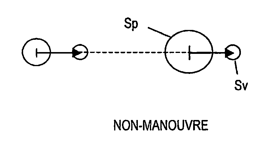
Another problem with IMM is that the mutual interaction between a “maneuver model” and a “non maneuver model”.
Should a maneuver occur, this may lead to track loss, if not the maneuver gate has been enlarged by other means [see ref.

Method used


Image

  • Model set adaptation by probability mass diffusion
  • Model set adaptation by probability mass diffusion
  • Model set adaptation by probability mass diffusion

Examples


Embodiment Construction

[0112]The invention concerns a new concept—denoted the “probability mass diffusion” (PMD) principle—for re-arranging the model set after the measurement updates.

[0113]The present invention, shall initially be explained in more detail by focusing on the computational workings and effects in close relation to the IMM method as applied to a number of exemplary radar applications, while later expanding the description to general applications where recursive estimation of dynamic systems / signals are used.

[0114]For this purpose we shall initially focus on four examples, in which the same complementary model / subset model is used for the PMD method and the IMM method, respectively and where the measurements fall either clearly within a given model or in an ambiguous area between models, respectively.

[0115]The indices are the same as defined above for FIGS. 16-21, except that being expanded with suffix a denoting the re-arranged model sets.

[0116]The IMM and the proposed method are equal in t...


PUM


Abstract

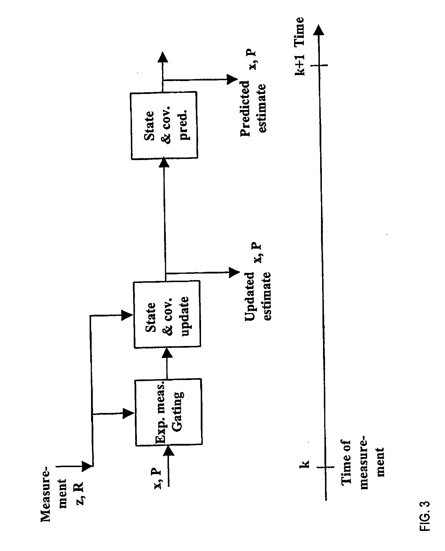
A method of performing a sequence of measurements, z, R; M; (t1,t2), of at least one parameter and recursively performing predictions. The method comprising the steps of—based on at least on a first measurement instance (M (tk); (k)), predicting the outcome (x, P) for at least two models (C, S); —after a subsequent measurement instance (M (tk+Tp)(k+Tp)) updating the models (C, S) for the corresponding point in time, whereby the prediction made on the basis of the first measurement instance is updated in the light of the subsequent measurement instance; and—re-arranging at least one model (C, S) for the subsequent measurement instance (tk+Tp) (k+Tp), whereby one updated model influences another updated model. For a model set comprising at least one complementary (C) model and at least one sub (S) model, under the step of rearranging the S model never influences the C model. For a model set comprising exclusively complementary (L, N, R) models, under the step of re-arranging, for a given pair of models within the model set (L, N, R), a model having a higher probability (μ) influences a model having a lesser probability, but wherein a model having a lesser probability (μ) never influences a model having a higher probability.

Description

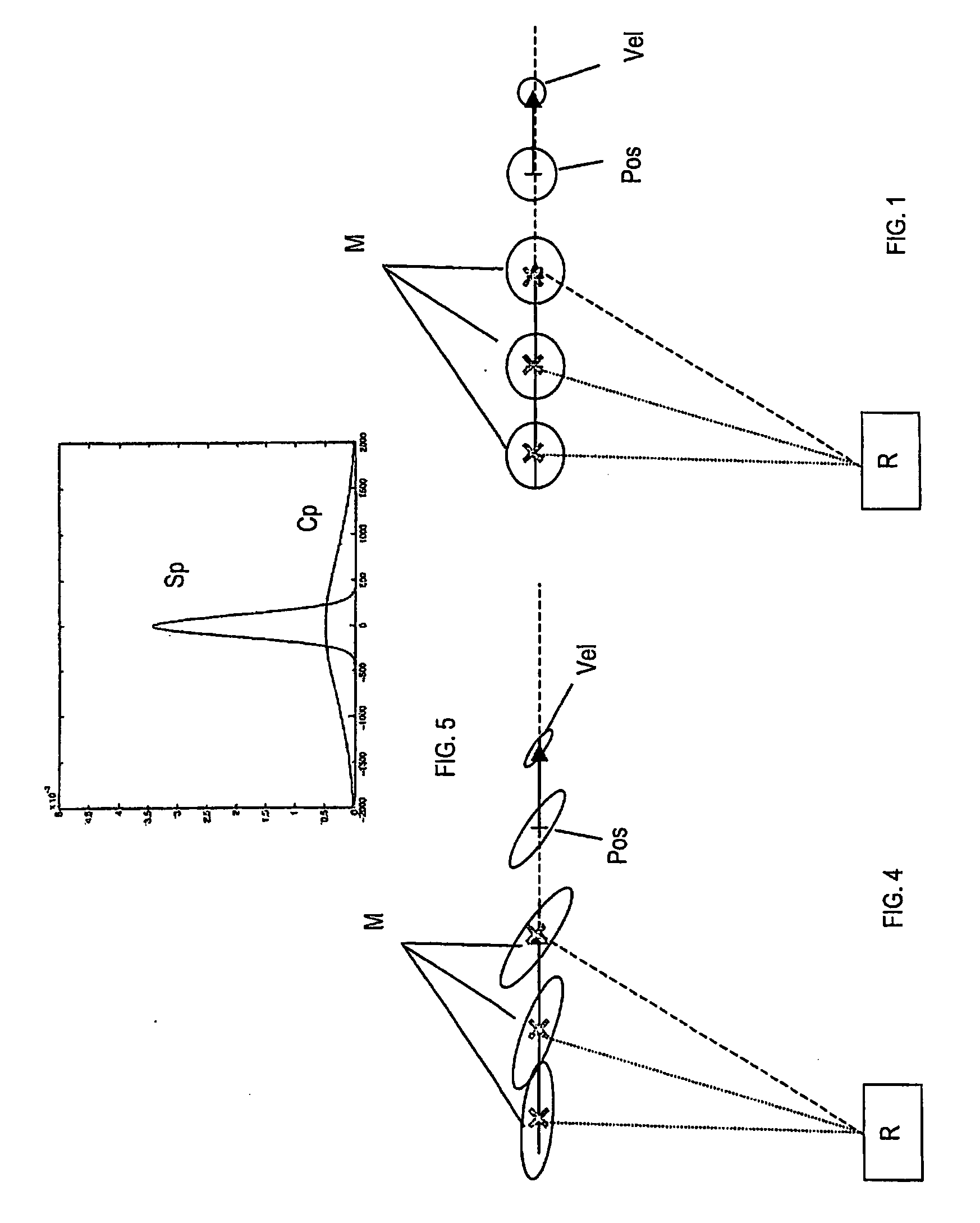
FIELD OF THE INVENTION[0001]The present invention relates to prediction based on stochastic models, and more particularly to recursive methods, that is, prediction models repeatedly involving choosing among multiple statistical prediction models based on measurement data.[0002]More specifically, the present application may be applied in a radar system predicting two-dimensional movements of objects as seen from a birds view perspective, whereby the radar system is measuring for instance the position of an object and is predicting future values of the position and the velocity of the object.BACKGROUND OF THE INVENTION[0003]FIG. 1, is a birds view representation of a radar system R observing the position of a flying object. A number of observations are made by the radar system. As indicated in FIG. 1, the measured position M may be associated with a given measurement accuracy, which again may be approximated by a circular Gaussian probability density function (PDF), two examples of wh...

Claims


Application Information

Patent Timeline
IPC IPC(8): G06F17/10
CPCG06F17/18G01S13/723
Inventor KRONHAMN, THOMAS
Owner KRONHAMN THOMAS
Learn More