Exhaust Gas Purification Device For Internal Combustion Engine

Inactive Publication Date: 2009-02-26
TOYOTA JIDOSHA KK
View PDF11 Cites 29 Cited by
  • Summary
  • Abstract
  • Description
  • Claims
  • Application Information

AI Technical Summary

Benefits of technology

[0004]It is, therefore, an object of the present invention to provide an exhaust gas purification device for an internal combustion engi

Problems solved by technology

However, for example if an engine is idled for a long time, the temperature of the NOx absorbent is lowered since the temperature of exhaust gas inflowing through the NOx absorben

Method used


Image

  • Exhaust Gas Purification Device For Internal Combustion Engine
  • Exhaust Gas Purification Device For Internal Combustion Engine
  • Exhaust Gas Purification Device For Internal Combustion Engine

Examples


Embodiment Construction

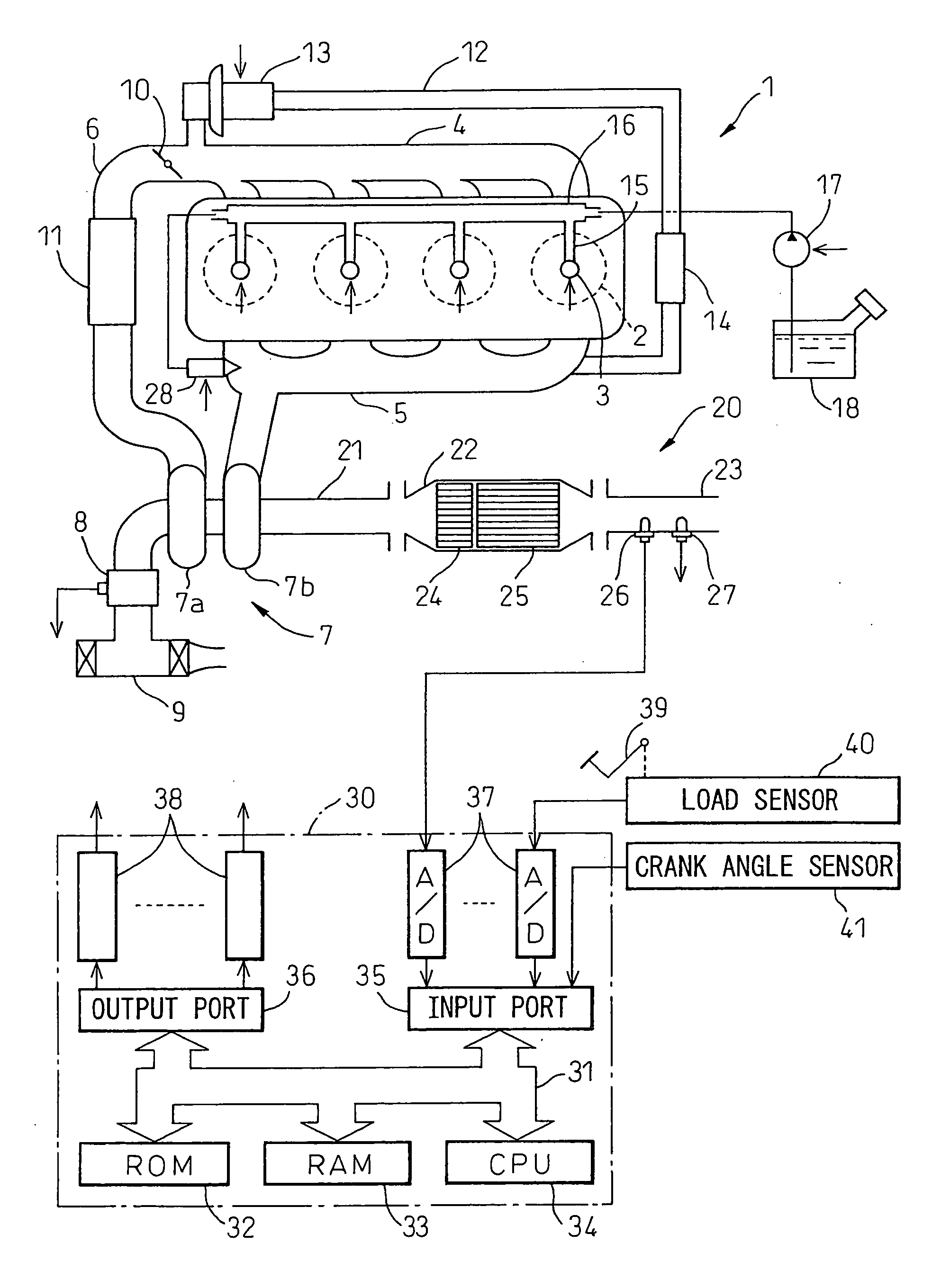
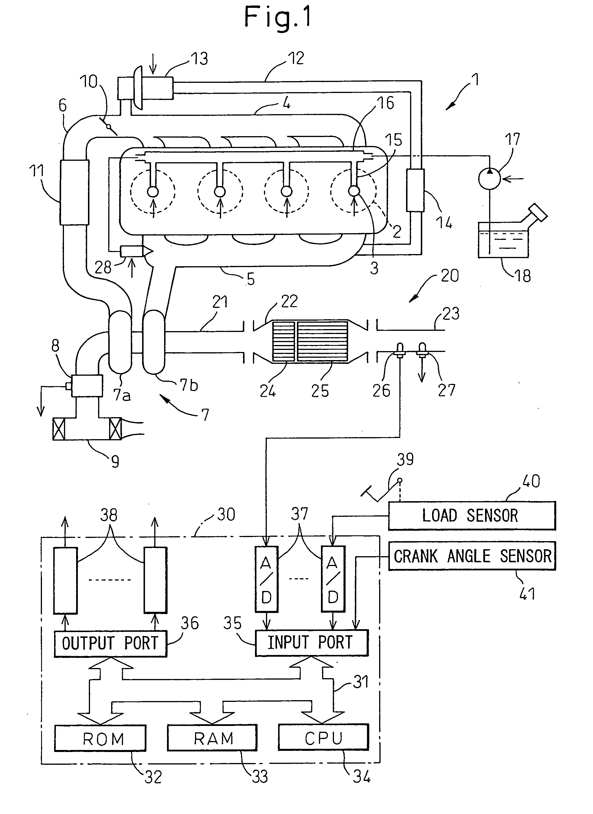
[0016]FIG. 1 illustrates a case where the present invention is applied to an internal combustion engine with a compression type ignition. Alternatively, the present invention may also be applied to an internal combustion engine with a spark type ignition.

[0017]Referring to FIG. 1, numeral 1 indicates an engine body, 2 a combustion chamber of each cylinder, 3 an electrically-controlled fuel injector for injecting fuel into each combustion chamber 2, 4 an intake manifold, and 5 an exhaust manifold. The intake manifold 4 is connected through an intake duct 6 to an outlet of a compressor 7a of a turbocharger 7. The inlet of the compressor 7a is connected via an air flow meter 8 to an air cleaner 9. An electrically-controlled throttle valve 10 is arranged in the intake duct 6. Further, a cooling device 11 is arranged around the intake duct 6 for cooling intake air flowing through the intake duct 6. In the embodiment shown in FIG. 1, engine cooling water is guided into the cooling device ...


PUM


Abstract

A NOx absorbent is arranged in an exhaust passage of an internal combustion engine, and a fuel supply valve (28) is arranged in the exhaust passage upstream of the NOx absorbent. If the temperature of the NOx absorbent is lower than a predetermined temperature when the NOx must be released from the NOx absorbent, the air-fuel ratio of exhaust gas flowing through the NOx absorbent is first switched from a basic lean air-fuel ratio to and maintained at a lean air-fuel ratio with a lower leanness for a predetermined lean time, and is then switched to a rich air-fuel ratio. If the temperature of the NOx absorbent is higher than the predetermined temperature when the NOx must be released from the NOx absorbent, the air-fuel ratio of the exhaust gas flowing through the NOx absorbent is switched to the rich air-fuel ratio without being switched to the lean air-fuel ratio with a lower leanness.

Description

FIELD OF THE INVENTION[0001]The present invention relates to an exhaust gas purification device for an internal combustion engine.BACKGROUND ART[0002]There is known an internal combustion engine wherein a NOx absorbent is arranged in the exhaust passage of the engine in which an NOx absorbent absorbs NOx contained in the exhaust gas therein when the air-fuel ratio of the exhaust gas is lean and releases absorbed NOx therefrom when the air-fuel ratio of the exhaust gas is switched to rich, wherein a fuel supply valve is arranged in the exhaust passage upstream of the NOx absorbent, and wherein fuel is supplied from the fuel supply valve to the NOx absorbent to make the air-fuel ratio of exhaust gas flowing through the NOx absorbent temporarily rich, when the NOx must be released from the NOx absorbent (see Japanese Unexamined Patent Publication No. 11-62666, for example). In the engine, NOx generated when combustion is carried out under a lean air-fuel ratio is absorbed in the NOx ab...

Claims


Application Information

Patent Timeline
IPC IPC(8): F01N9/00
CPCF01N3/0842F01N3/0871F01N2250/14F01N2610/03Y02T10/26F02D41/024F02D41/0275F02D2200/0802F02B37/00Y02T10/12
Inventor OHASHI, NOBUMOTO
Owner TOYOTA JIDOSHA KK
Why Eureka
Try Eureka