Modular Microfluidic Flow Cytometer and Method Applications

a flow cytometer and microfluidic technology, applied in the field of flow cytometry, can solve the problems of difficult adapting systems to use with infectious diseases or pathogenic microorganism samples, requiring extensive time, expertise and expense, etc., and achieves the effects of reducing the overall cost of instruments, improving the portability of systems, and facilitating the use of flow cytometry

Inactive Publication Date: 2009-02-26
AGAVE BIOSYST
View PDF6 Cites 46 Cited by
  • Summary
  • Abstract
  • Description
  • Claims
  • Application Information

AI Technical Summary

Benefits of technology

[0011]The system advantageously provides a vast improvement over many of the fundamental limitations of current flow cytometry systems, not the least of which includes direct mounting on a microscope for use in virtually any environment. The ability to use this system on a preconfigured microscope dramatically reduces the overall cost of the instrumentation and opens up the utility of flow cytometry to any facility that has an existing microscope. The modular design of the system increases the portability of the system, making it ideal for use in, e.g., a bio-safety containment chamber, for field applications, and in developing countries where the cost and infrastructure associated with traditional flow cytometers make their use less feasible.

Problems solved by technology

Some of the disadvantages of these systems are that they are quite expensive ($100 k-$750 k), they are large and not portable, and they require extensive time, expertise, and expense to use and maintain.
Additionally, the open flow design (and hence the aspirated liquid that is an obligatory by-product of this design) used by many major flow cytometry manufacturers, makes these systems difficult to adapt for use with infectious disease or pathogenic microbiological samples.

Method used


Image

  • Modular Microfluidic Flow Cytometer and Method Applications
  • Modular Microfluidic Flow Cytometer and Method Applications
  • Modular Microfluidic Flow Cytometer and Method Applications

Examples


Embodiment Construction

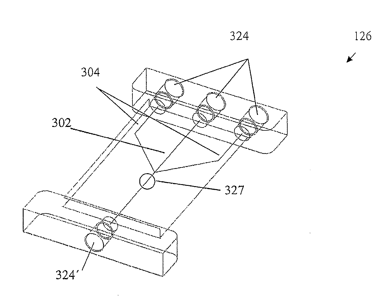
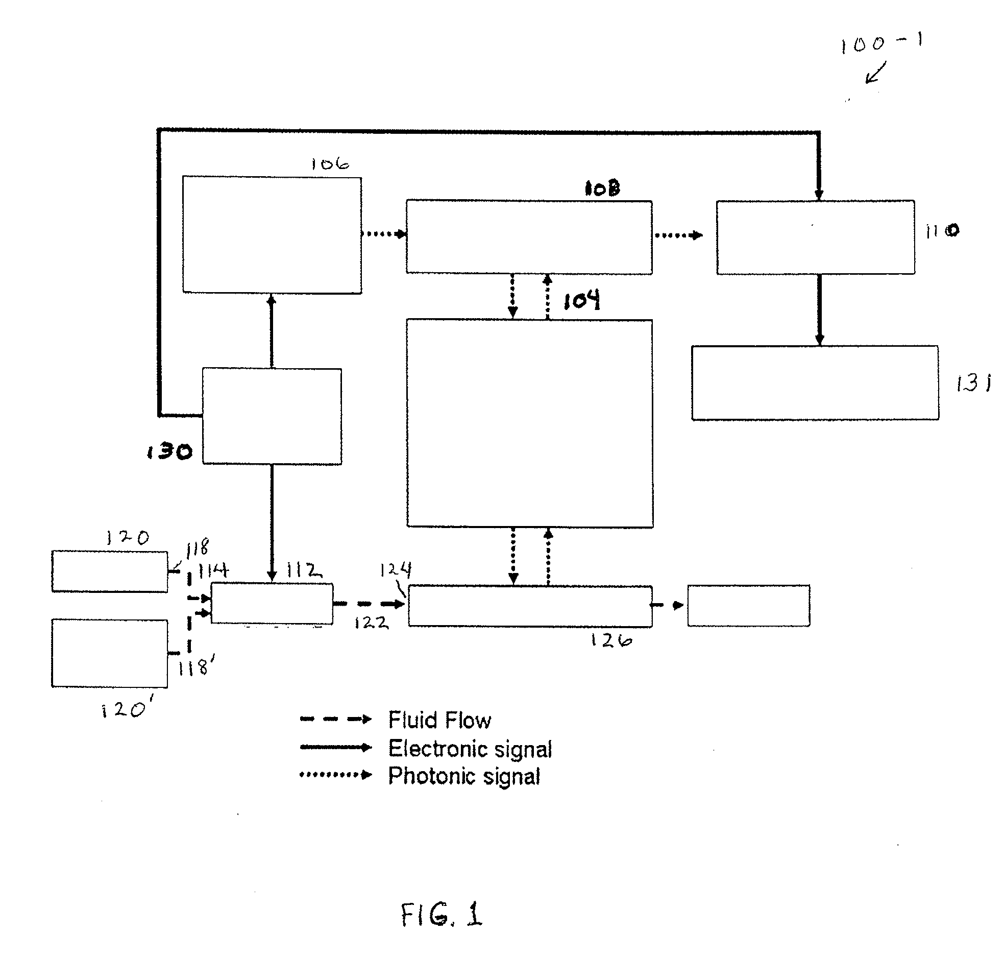
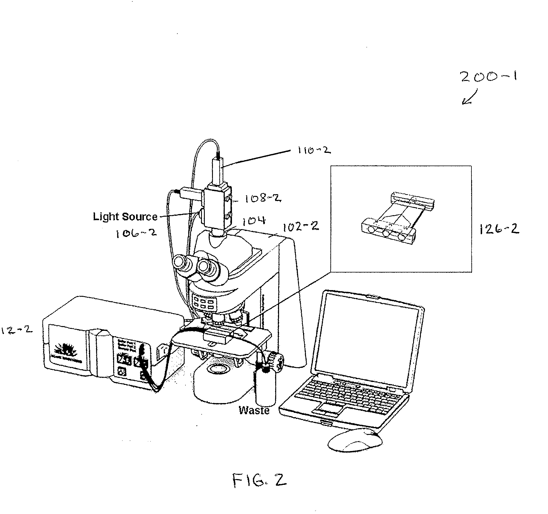
[0019]An illustrative portable, modularized flow cytometry apparatus 100-1 is schematically illustrated in FIG. 1. The system includes a microscope platform 102 including an optical input / output port(s) 104, imaging optics (per standard microscope optics; see FIG. 2), and a sample (specimen) stage (per standard microscope stage; see FIG. 2); a sample illumination source module 106 that is removably integrated with the optical input / output port; an optics module 108 that is removably integrated with the sample excitation light source module and the optical input / output port; a detector module 110 that is removably integrated with the optics module and the optical input / output port; a fluidic pump module 112 having a fluidic input 114 and a fluidic output 116, a first removable fluid conduit 118 for connecting a fluid source 120 (and, as shown, a sheath buffer 120′ via a removable fluid conduit 118′) to the input, and a second removable fluid conduit 122 for connecting the output to a...


PUM

PropertyMeasurementUnit
angleaaaaaaaaaa
flow rateaaaaaaaaaa
angleaaaaaaaaaa

Abstract

An embodiment of the invention is directed to a portable, modular, microscope mounted, microfluidic flow cytometry system. The system includes a microscope platform having an optical input/output port, imaging optics, and a sample stage; a sample illumination source module that is removably integrated with the optical input/output port; an optics module that is removably integrated with the sample excitation light source module and the optical input/output port; a detector module that is removably integrated with the optics module and the optical input/output port; a fluidic pump module having a fluidic input and a fluidic output, a first removable fluid conduit for connecting a fluid source to the input, and a second removable fluid conduit for connecting the output to an input of a microfluidic flow module; and, a system control and programmable data processing module. The system may further incorporate a microfluidic flow module positionable on the microscope sample stage having an output removably connectable to a fluidic waste collector. Method embodiments relating to applications of the microscope-mounted microfluidic flow cytometry system are also described.

Description

CROSS-REFERENCE TO RELATED APPLICATIONS[0001]This application claims priority to U.S. Provisional application No. 60 / 827,751 filed on Oct. 2, 2006 under 35 USC § 119, the content of which is herein incorporated by reference in its entirety.STATEMENT REGARDING FEDERALLY SPONSORED RESEARCH OR DEVELOPMENT[0002]This invention was made with Government support under contract no. NAS2-02045 awarded by the National Aeronautics and Space Administration and contract no. HHSN261200555000C awarded by the National Cancer Institute, National Institutes of Health. The Government has certain rights in the invention.BACKGROUND OF THE INVENTION[0003]1. Technical Field[0004]Embodiments of the invention are generally directed to the field of flow cytometry. More particularly, embodiments of the invention are directed to modularized flow cytometry apparatus and methods that are more efficient, less costly, and otherwise improved over traditional flow cytometry systems.[0005]2. Background Art[0006]Flow c...

Claims


Application Information

Patent Timeline
Patent Type & Authority Applications(United States)
IPC IPC(8): G01N21/05
CPCG01N15/147G01N15/1484G01N15/1475
Inventor SALAZAR, NOE ANTONIOTABB, JOEL SAMUEL
Owner AGAVE BIOSYST
Why Eureka
Try Eureka